Wave Forces Calculator

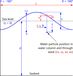
Fig 1. Wave profile
This calculator is exactly the same as Waves, but with the additional facility for converting wave velocities and accelerations into forces on a structural member, both through the wave and through the water column (top to bottom of member).
Waves+ is not intended as a supplement to Waves, as both calculators give the same results for water particle movement.
Waves+ is only required if you need wave forces due to water particle movement.
Wave Theory
The hydrodynamic theories in the Waves+ calculator are identical to those described in Waves, the support for which is provided in its technical help page.
Force Theory
This calculator uses Morison's hydrodynamic loading formulas for drag and added mass to convert water movement to horizontal and vertical load on a structural member throughout its depth.
The Structural Member

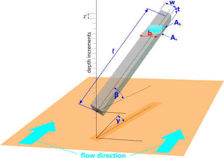
Fig 2. Submerged Structural Member
The wave load is applied both horizontally and vertically along the length of a structural member of constant cross-section.
Due to the infinite range of potential cross-sections, CalQlata has left it up to you (the user) to enter the horizontal and vertical cross-sectional areas (Aₕ & Aᵥ) and projected width (b) for the member at the preferred inclination and orientation. However, Waves+ does calculate these values for rectangular and elliptical members should you wish to use them.
Some useful tips in calculating these values are provided below (Fig 2):
The horizontal and vertical cross-sectional areas (Aₕ & Aᵥ) are applied only to the added mass calculation; Displaced Volume = area x z'
The horizontal and vertical projected width (b) is applied only to the drag calculation; Projected Area = b x z'
At any given orientation (γ), the horizontal and vertical cross-sectional areas remain constant, irrespective of depth:
The horizontal cross-sectional area through the member @ 'β':
Aₕ = w . √[ {ℓ.Cos(β)}² + {t.Sin(β)}² ]
The vertical cross-sectional area through the member @ 'β':
Aᵥ = w . √[ {t.Cos(β)}² + {ℓ.Sin(β)}² ]
At any given inclination (β), the projected width (b) is the same (horizontally and vertically) irrespective of depth:
If a = √[ w² + t² + {t.Tan(β)}² ];
The projected width @ 'γ': b = a . Cos[ Acos(w/a) - γ ]
Whilst you may enter any values you wish for the cross-sectional areas (Aₕ & Aᵥ) and projected width (b), Waves+ calculates them for rectangular and elliptical members based upon the above calculation procedure, just in case you wish to use them.
When dealing with unusual cross-sections, you may find it more convenient to alter the member's coefficients rather than its dimensions. I.e. instead of modifying Aₕ, Aᵥ & b, you could modify Cdₕ, Cdᵥ and Caₕ, Caᵥ. For example; if you feel that the projected width and/or cross-sectional areas are likely to be less than those calculated (above) for a given direction (horizontal or vertical), you should reduce Ca accordingly, and vice versa. The same goes for projected width and Cd.
For your information, the projected width (b) of an inclined member with an elliptical cross-section is 1/√2 times the projected width of a rectangular member of the same proportions (width:thickness). Therefore, if your member is elliptical in section, you should multiply either 'Cd' or 'b' for a rectangular cross-section by 0.7071. The same applies to the cross-sectional areas (Aₕ & Aᵥ), but in this case; the multiplier is π/4 (0.785398163)
When dealing with special cases, for example; vertical members attached to the seabed (such as piles), the vertical cross-sectional area may be ignored (Aᵥ=0), and/or the vertical drag coefficient (Cdᵥ) may be set to a suitably low value (e.g. 0.1) to account for longitudinal surface drag.
Summary
The following represents the limitations and potentials for the Waves+ calculator:
1) The forces are plotted as 'Fx,Fy' through the wave and through the water column.
2) The depth-increments are provided over the inclined height of the structural member.
3) The coincident angle through the wave at z', which is dependent upon inclination and orientation, is also provided.
4) Structural members are assumed to have a constant cross-section.
5) Structural members may be exposed to the wave at any inclination and/or orientation.
6) Non-uniform structural members may be accommodated by playing with the coefficients for Cd and Ca.
7) The properties of the wave are the same as those calculated in the Waves calculator.
8) The stresses in the structural member may be found through post-processing of these forces in a suitable spreadsheet (e.g. Microsoft's Excel).
Waves+ Calculator - Technical Help
In order to view the forces calculated, you need to open the 'Data' menu and select submenu item 'Forces: z,θ; Fx,Fy'
Units
You may use any units you like, but you must be consistent. Also, remember that the results you get will be in the same units you entered.
Input Data
The following input data applies to the instantaneous water particle properties list in the output data:
d = water depth from seabed to sealevel (flat-water)
h = wave height from trough to peak
p = wave period from -180° to +180°
z = distance from sealevel (-z = below and +z = above)
θ = angle through wave; -180° ≤ θ ≤ 180°
cur = speed of current in the direction of the wave
g = acceleration due to gravity
The following input data applies to the forces plotted in the menu item: 'Data>Forces; z,θ; Fx,Fy'
Cdₕ = drag coefficient in horizontal direction #
Cdᵥ = drag coefficient in vertical direction #
Caₕ = added mass coefficient in horizontal direction ##
Caᵥ = added mass coefficient in vertical direction ##
ρ = density of medium (e.g. seawater ≈ 1025 kg/m³ or 64 lb/ft³)
H = height above seabed of bottom of structural member
w = width of structural member; dimension normal to wave direction @ γ=0
t = thickness of structural member; dimension normal to w
ℓ = length of structural member
b = projected width of structural member @ 'β' normal to wave direction
Aₕ = horizontal cross-sectional area @ 'β' of structural member
Aᵥ = vertical cross-sectional area @ 'β' of structural member
β = inclination of structural member (0°<β<90°; β = 90° = vertical)
γ = orientation of structural member (0°≤γ≤90°; γ = 0° = parallel to wave direction)
i = force plot increments; applies to both through the wave and through the water column (20≤i≤360)
# normally 0.7≤Cd≤1.0 for elliptical to rectangular sections respectively
## normally 0.5≤Ca≤1.0 for curved to flat sections respectively (Ca refers to the shape effect, 1.0 is added to the entered value to account for the displaced volume)
Output Data
L = wave length; between adjacent peaks
t = wave period; between adjacent peaks
x = distance through wave (from wave peak)
k = wave number
ω = wave angular velocity
c = wave celerity (speed)
η = wave profile (height above sealevel) @ x
vx = water particle horizontal velocity @ x,z
vz = water particle vertical velocity @ x,z
ax = water particle horizontal acceleration velocity @ x,z
az = water particle vertical acceleration velocity @ x,z
α = wave slope (angle of surface water) @ x
b = projected width (calculated for a rectangular member) that may be entered (b) if preferred
Aₕ = horizontal cross-sectional area (calculated for a rectangular member) that may be entered (Aₕ) if preferred
Aᵥ = vertical cross-sectional area (calculated for a rectangular member) that may be entered (Aᵥ) if preferred
b = projected width (calculated for an elliptical member) that may be entered (b) if preferred
Aₕ = horizontal cross-sectional area (calculated for an elliptical member) that may be entered (Aₕ) if preferred
Aᵥ = vertical cross-sectional area (calculated for an elliptical member) that may be entered (Aᵥ) if preferred
The output data for the forces are to be found via menu item: 'Data>Forces: z,θ; Fx,Fy'.
The individual loads presented apply only to the increment z',θ displayed in the list. The total [horizontal/vertical] load on the structural member is the sum of the forces listed.
Applicability
The applicability of the (water particle) properties is as described (for each theory) for the Waves calculator.
The forces calculated in Waves+ apply to a single structural member of constant cross-section configured at any inclination and/or orientation.
Accuracy
The accuracy of the wave (water particle) properties is as defined by the creators of the applicable theory.
The accuracy of the forces is as defined by Morison, the creator of the theory. However, accuracy is also heavily dependent upon applicable coefficient values for drag and added mass.
Further Reading
You will find further reading on this subject in reference publications(6, 8 & 9)

