emf to mmf and back
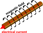
Fig 1. emf to mmf
This page describes the relationship between electricity and magnetism as it applies to solenoids, transformers, motors and generators.
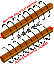
Fig 2. Compound mmf
Electricity and magnetism are essential converses (equal and opposite), and mutually exclusive (one cannot be converted to the other) and mutually inclusive (one cannot exist without the other)
An important distinction between both is that electrical charges are shared between adjacent particles and magnetic charges are accrued.
Electrical power comes from electrical charge, which can be released as either:
1) The transfer of electrons between the atoms in a conductor (DC); or,
2) The generation of electro-magnetic energy (AC).
Magnetic power comes from magnetic charge, which can be released as either:
1) The transfer of magnetic charge energy between atomic particles; or,
2) The exploitation of magnetic-field energy (B) in a ferro-magnetic material.
Electricity: current = emf x resistance
Magnetism: flux = mmf x reluctance
| Property: | Electrical | Units | Magnetic | Units |
|---|---|---|---|---|
| Flow rate | Current | C/s | Flux | Wb |
| Impediment to direct flow | Resistance | J.s/C² | Reluctance | J / s.Wb² |
| Force needed to overcome impediment | Electro-motive force | J/C | Magneto-motive force | J / s.Wb |
| Indirect energy transfer # | Field | kg/C | Field | kg / s.Wb |
| Capacity of field flow | Permittivity | C² / J.m | Permeance | (s.Wb)² / J.m |
| Field density (energy storage) | Capacitance | kg.m²/C² | Inductance | kg.m²/(s.Wb)² |
| Electricity and Magnetism C = Coulomb & Wb = Weber Note: kg.m²/C² = J/A |
||||
# the term 'Field' as described above, is actually the reciprocal of relative charge capacity (RC); B = 1/RC and its units are C/kg or Wb/kg.
The Principles
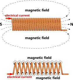
Fig 3. Tight and Loose Coils
A current passing through a conductor will always generate an encircling magnetic field according to the right-hand rule (Fig 1).

Fig 4. A Basic Solenoid
If two conductors are run alongside each other and a current is induced in both of them (e.g. a return loop), the magnetic fields generated around them will work together (in opposite directions) increasing their combined strength (Fig 2).
A conductor wound into a tight coil with a current passing through it, will generate a magnetic field as shown in Fig 3. Note, an open coil will generate a coiled version of Fig 1 in which adjacent magnetic fields will cancel each other out as they will be flowing in the same direction (Fig 3).
Insert a bar of magnetic material into the tight coil, and the bar will become magnetised (Fig 4). It should be noted that when defining the north-pole of the resulting [electro-]magnet, the direction of the current in the conductor is immaterial. The defining factor is the direction around which the current orbits the coil.
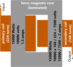
Fig 5. Transformer
Electrical power is the product of current and voltage; p = V.A
The same power may be achieved by; raising the current and similarly reducing the voltage (and vice-versa), as long as their product remains the same. But because current is more susceptible to resistance than voltage, the most efficient method for transmitting electrical power along a very long conductor is to maximise its voltage and minimise its current. When the power is required to do work, you reverse this process. This can be done by utilising the electro-magnetic properties of a coil (Fig 5) in the form of a transformer; the transformation of electrical power.
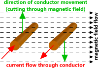
Fig 6. mmf to emf
Stepping voltage up or down can be accomplished by wrapping coils around a common ferro-magnetic core (Fig 5). The current passing through the input coil will (via its magnetic field) generate a magnetic flux in the core, which will induce an electrical current in the output coil. The relative number of turns in each coil will determine the voltage - and therefore the current - in the output conductor. Increasing the voltage requires a greater number of turns in the output coil and vice-versa.
A current will be induced in a [moving] conductor passing through a magnetic field as shown in Fig 6. The nature of the energy transfer in a transformer is the conversion and transfer of; electrical force to magnetic force and back to electrical force. The electrical force is termed voltage (electro-motive) and the magnetic force is simply referred to as magneto-motive [force].
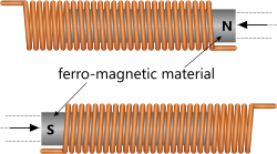
Fig 7. A Simple Generator
If you move a permanent magnet within a tight [conductive] coil, a current will be induced in the conductor (Fig 7). Lenz’s law states that the magnetism and the electrical current are together trying to maintain a steady state. Induce movement in the magnet to upset this steady-state and the electrical current will oppose the movement.
All of the above is called electro-magnetic induction and was discovered by Hans Christian Ørsted in 1820 and explained by Michael Faraday in 1831. This phenomenon is the basis of all motors and generators.
Transformers
Electrical transformers convert between a dominance of current (I) and Voltage (V), the respective magnitudes of which, are dependent upon the relative number of input and output coils (Fig 5; turns). In other words, as voltage increases, current decreases, and vice versa.
The purpose of an electrical distribution transformer is to minimise the energy losses that occur during transmission over long distances, the lower the current, the lower the losses. So, high source current is converted to high Voltage before transmission, and reversed afterwards.
Despite these relative variations in magnitude, electro-magnetic power (P = V.I) remains unchanged during transmission; apart from unavoidable losses. So, the available magnetic potential energy (PE = P/ƒ = F.d) will also remain constant; conservation of energy.
Therefore, if magnetic force increases with increasing current (F = μ.I²), its effective distance (field) must reduce, and vice versa, which is the reason solenoid [plunger] strengths reduce as assembly clearances increase.
The primary advantage with electro-magnets is that they can be switched on and off; such as in solenoids.
Further Reading
You will find further reading on this subject in reference publications(3, 17 & 22)