Low Friction Bearing Calculator (ball & roller)
Ball and roller bearings are collectively called 'low-friction' bearings because of their very low start-up friction and very low rolling resistance. They are specified by ANSI/ABMA in their AFBMA standards. However, given that these bearings have small contact areas the contact stresses are higher than for, say; plain bearings and excessive loads will cause the balls or rollers to indent bearing cage(s) increasing rolling resistance and likelihood of premature failure.
The principal limiting factors for general low-friction bearings are the maximum static and/or dynamic load ratings and the life-rating (L₁₀), speed and accuracy being reserved for specialist applications. The static and dynamic load ratings are calculated to ensure that no component in the bearing assembly will deform to a point that the life rating is threatened.
The fatigue life of these bearings is defined by their ability to maintain shape whilst rotating under load. This, in turn, is dependent upon the efficiency of the lubrication (all low-friction bearings require high-quality lubrication; see Lubrication below), the accuracy of the manufactured components and their material integrity. If all these conditions are appropriate, there is no practical limit to a ball or roller bearing’s rotational speed. However, the faster they rotate, the faster the bearing will exceed its life rating.
Ball Bearings

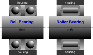
Fig 1. Radial Bearings
Ball bearings are a low-friction device for two differentially-rotating bodies. They are narrower than roller bearings and normally comprise a hardened inner case, a hardened outer case and a number of high-strength, very hard ball bearings, all of which are normally held together by a specially designed 'race'.
Most common ball bearings are of the 'Deep-Groove' type and normally called the 'single-row, non-filling slot' or 'Conrad' type. Radial ball bearings are not normally used for purely axial loading conditions because they are not self-aligning so you would need to incorporate secondary shaft-housing alignment system in addition to the bearing, which would increase frictional resistance.
Ball bearings are usually designed to accommodate predominantly radial loading conditions.
Roller Bearings
Roller bearings are a low-friction device for two counter-rotating bodies. They are wider than ball bearings and normally comprise a hardened inner case, a hardened outer case and a number of high-strength, very hard roller bearings, all of which are normally held together by a specially designed ‘race’.
Most common roller bearings can be used for purely radial or purely axial loading applications along with any combination of the two. Roller bearings are naturally self-aligning and able to support much higher dynamic and static loads than ball bearings of the same diameter.
Roller bearings are not normally able to sustain the same high-speeds as an equivalent ball bearing.
Radial Bearing
A radial bearing (Fig 1) is one that is designed to sustain applied loads at right-angles to the axis of rotation. Most radial ball bearings can support an oblique applied load, but usually limited to less than 30°. There is no such limitation for radial roller bearings.
Thrust Bearing

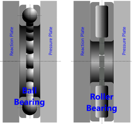
Fig 2. Thrust Bearings
A thrust bearing (Fig 2) is one that is designed to sustain applied loads parallel to the axis of rotation. All thrust bearings can support an oblique applied load of any angle.
Whilst roller bearings are usually preferred for thrust applications due to their higher loading capacity, the outer rotational diameter of each roller tries to spin faster than its inner rotational diameter, thereby causing the rollers to skid in one end or the other, so in thrust bearings, rollers tend to be angled (coned) to compensate for this problem.
Lubrication
Excellent and constant lubrication is essential for low-friction bearings to achieve their life rating.
Grease is normally recommended for bearings that must be periodically re-lubricated or 'sealed' for life and/or operate under heavy loads.
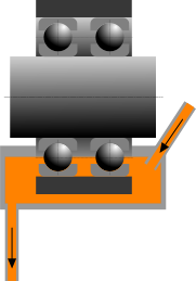
Oil is recommended for ball and roller bearings only if the loads are very low and a viscous oil can be flushed and cleaned (filtered) continuously (Fig 3). Such lubrication systems allow ball and roller bearing assemblies to rotate at much higher speeds or significantly extend their life rating.
Bearings – Technical Help
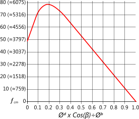
This calculator applies formulas similar to those originally devised by Palmgren in 1924 but with factors updated by ABMA in 1990⁽¹⁾, therefore, should you be unable to verify exact comparison results with your own hand calculations, you should first check that you are not using Lundberg and Palmgren’s original factors for the material and geometry (ƒ known originally as ƒc and now referred to as ƒcm). Fig 4 shows the relationship between this factor and the diametral relationship between the rolling elements. As can be seen in Fig 4 a diametral relationship of 0.19 provides the highest factor and therefore the best life rating.
Our Bearings calculator is designed to provide recognised load and life ratings for all general applications. However, where specialist applications require the use of non-standard bearings, you should always verify your designs giving due consideration to the design requirements from the bearing manufacturer.

Fig 3. Flushing Lubricator
When calculating, you must verify that the following conditions apply:
P < C
F < Cₒ
σᶜ < 4000MPa (580,000psi)
L₁₀ / RPM / 60 > the hours you expect your bearing to last
It is important to remember that ‘RPM’ mentioned above is the difference between the rotational speeds of the inner and outer bearing cages.
Units
You may use any units you like, but you must be consistent.
Radial Ball Bearings
These calculations apply to all ball bearings fitted to a shaft with an outer housing that rotate relative to each other.
Double-row ball bearing assemblies should be treated similarly to two adjacent individual ball bearings
Thrust Ball Bearings
These calculations apply to all ball bearings fitted to a plate or shaft with an opposing plate or shaft that rotate relative to each other but with a load applied along the axis of the plates or shafts.
Radial Roller Bearings
These calculations apply to all roller bearings fitted to a shaft with an outer housing that rotate relative to each other.
Thrust Roller Bearings
These calculations apply to all roller bearings fitted to a plate or shaft with an opposing plate or shaft that rotate relative to each other but with a load applied along the axis of the plates or shafts.
Machining Tolerances
Bearings tells you the most appropriate class of 'fit' for the shaft as it is easily predicted on the basis of light, normal or heavy loading condition relative to the shaft diameter. You can calculate the associated machining tolerances for the recommended fit using CalQlata’s Limits & Fits calculator. This is not the case for the housing, however, the class of 'fit' for which is dependent upon the housing design.

Fig 4. Diametral Relationship vs Factor 'ʄcm'
The recommended class of fit for various housing design configurations is listed below:
Outer ring stationary relative to load:
non-shock loads > split housing = H7
non-shock loads > one piece housing = H6
shock loads > one piece housing = J6
Variable load direction (one piece housing)
non-shock loads = J6
heavy shock loads = K6
Outer ring rotating relative to load (one piece housing)
light loads = M6
normal loads = N6
heavy loads = P6
Applicability
This calculator applies to all general purpose applications for all ball and roller, radial and thrust bearings. For specialist applications, e.g. particularly high speeds, higher than normal levels of accuracy or life expectancy or especially difficult operating conditions, you should always consult the bearing supplier for the most appropriate products.
Accuracy
Bearings' calculation accuracy is statistically the same as that originally expected by Lundberg and Palmgren, along with the factors generated by ABMA so long as the machined fit and operational conditions (loads and lubrication) are maintained throughout the operating life of the bearing and that its materials are of the same standard as those recommended by ABMA.
Notes
- The factors listed in reference publication 2 are those originally recommended by Palmgren in 1924. These values have since been superseded by the AFBMA standards. It is these superseded values that are included in the Bearings calculator
- The formulas listed in reference publication 1 contain errors and as such should be used with caution
- The value associated with L₁₀ represents the number of millions of revolutions a bearing should survive with at least 90% of its rolling elements still intact
Further Reading
You will find further reading on this subject in reference publications(1 & 2)

