Vortices Calculator (free and forced)
Vortices are natural (free) or unnatural (forced) fluid spirals.
They appear, or occur, either as a result of fluid flow through a duct (Stokes) or around objects (Strouhal). Apart from the constant of motion (K), which is a fundamental natural law, the mathematics associated with these phenomena can only ever be approximate, and their accuracy is dependent upon the presence of disturbance.
That said, the formulas used in this calculator are those that are generally accepted by industry and academia alike.
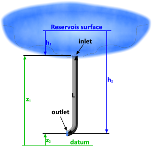
Fig 1. Fluid Flow Through a Riser
Bernoulli
Bernoulli generated the most intelligible formulas that relate the properties of a fluid at both ends of any duct through which it passes:
h = h₁ + z₁ + v₁²/2.g = h₂ + z₂ + v₂²/2.g + hᴸ
p = p₁ + ρ.g.z₁ + ρ.v₁²/2 = p₂ + ρ.g.z₂ + ρ.v₂²/2 + pᴸ
Whilst this is a useful calculation option in its own right, it is included in Vortices to provide the common properties and constants that are needed for the other calculation options, along with the feed energy for a forced vortex.
The example illustrated in Fig 1 shows a reservoir emptying into a vertical pipe (riser) that may be used to power a pump or turbine, such as employed in hydraulic dams.
Vortices
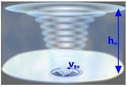
Fig 2. Free Vortex
A natural vortex is a rotating spiral of fluid (e.g. water or air), such as an emptying bath (plug) or a tornado.
Like the weather, there are always random forces and conditions present to make exact mathematical predictions very difficult. However, one predictable property of a vortex is its natural rotational direction.
A bath-plug type vortex (Fig 2) occurs naturally as a fluid exits under the influence of the earth's gravitational attraction and the moon's orbit (relative to the earth's surface rotation). This type of vortex is referred to as a free (or natural) vortex – gravity is its driver.
There is another type of vortex that is artificially generated and tends to be used to drive rotating equipment such as electrical generators or pumps (Fig 3). This is generally referred to as a forced (or unnatural) vortex.
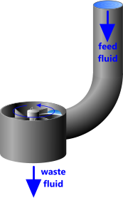
Fig 3. Forced Vortex
Whilst the strength of this type of vortex is also governed by fluid head, pressure, velocity, etc., its direction is governed by the orientation of the fluid entry. And although the natural Coriolis force can be discounted as a significant driver in such equipment, it would be unwise to drive any equipment counter to the natural rotational direction for a given hemisphere, because whilst insignificant, it is always more efficient to add this force than to subtract it. Therefore, it is always preferable to drive forced vortex equipment in an anti-clockwise direction in the northern hemisphere and clockwise in the southern hemisphere.
Vortices are frequently used to measure fluid flow, which may be based upon vortex shedding around a specially profiled bar installed in the flow-path normal to flow-direction, or forced vortex flow meters which work on the principle of a centrifugal fan or pump working in reverse. But because fluid flow can be measured using spheres, this calculation option has also been included in Vortices.
Constant of Motion (K)
You will frequently see this constant referred to as circularity or circulation when applied to vortices, however; because they are orbital, natural vortices obey the same rules as those discovered and explained by Isaac Newton for celestial bodies. Their rotary motion is therefore governed by the same constant of motion.
Newton's constant of motion applies to all natural orbits; i.e. those driven by a force-centre, whether it be a star or a combination of Coriolis and flow. This is why the constant of motion applies to free [natural] vortices and not to forced [unnatural] vortices, which are not driven by a force-centre.
The relationship between velocity and radius in all such orbits looks like that described in Fig 7.
'K' applies throughout any given [free] vortex; right across its radius and down through its depth.
Vorticity (ζ)
A rotational vortex (Fig 4) is one in which the particles spin as they orbit the central axis. This can be demonstrated by floating a vane on the fluid surface; it will rotate as it orbits. All forced vortices are rotational giving them a vorticity of twice the angular velocity of the vortex.
Irrotational vortices are those in which the fluid particles do not spin or rotate as they orbit the central axis. This can be demonstrated by floating a vane on the fluid surface (Fig 7); it will not rotate as it orbits. All free vortices are irrotational giving them a vorticity of zero.
Forced Vortex
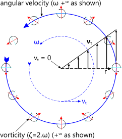
Fig 4. Rotational Vortex
As explained above, forced vortices are rotational.
Fluid particles rotate locally in the same direction as the global rotation of the vortex (Fig 4). These angular velocities are related thus;
Vorticity: ζ = 2.ω (ᶜ/s)
where ω (ᶜ/s) is vortex angular velocity
Because its fluid is driven across the radius or from the periphery, the angular velocity of the fluid is constant, resulting in a tangential velocity increasing linearly with radius as shown in Fig 4. Hence the kinetic energy in the rotating fluid increases with the square of the radius.
Because the surface profile of a forced vortex is dished as shown in Fig 10 - it sinks in the middle and rises towards the outer edge - it is important to take this into account when designing an impeller that will be driven by it.
Forced vortices are the obvious power source for hydro-dam generators; they rely on [natural] gravity to induce energy in a falling fluid, and apply this energy [unnaturally] directly across the face of impeller blades to drive a turbine, which is essentially a centrifugal fan working in reverse.
Free Vortex

Fig 5. Centrifugal Pressure
The spin in a free vortex occurs naturally due to gravitational force and the Coriolis effect of the moon's orbital direction relative to the earth's surface rotation, which is the reason vortex directions vary according to hemisphere; anti-clockwise in the north and clockwise in the south. Free vortex strength, however, is determined by the fluid head; the Coriolis effect only initiates spin, it does not drive it.
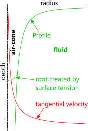
Fig 6. Free Vortex Profiles
Two competing pressures exist in a free vortex; centrifugal and gravitational. If at any point in the vortex centrifugal pressure (Fig 5) is greater, an air-cone will be generated at that radius (Fig 6). Theoretically, because the tangential velocity at the centre of the vortex is infinite, an air-cone should always exist full depth, as shown in Fig 6 (green-line), however, surface tension in the fluid will ensure that a root will form just below the surface if the vortex is weak, such as evidenced in an emptying domestic bath or sink.
Fig 6 shows how surface profile and tangential velocity vary with radius within a theoretical free vortex. If inlet and/or outlet flow are in anyway compromised; such as in a domestic bath or sink#, the profile will be unstable. A theoretical shape will only exist if the fluid reservoir and outlet path are free of encumbrances.
# note: plug-holes are normally sited close to a vertical surface and an S-Bend is installed immediately below the outlet
Tangential velocity in a free vortex is inversely proportional to the square of the distance from the centre (axis) of spin; i.e. it reduces parabolically towards the outside of the vortex (Fig 6 red-line).
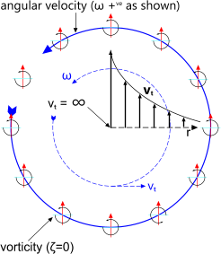
Fig 7. Irrotational Vortex
Because free vortices are irrotational (Fig 7); their vorticity is zero;
ζ = 0
The constant of motion, which applies to all free vortices, is defined thus;
K = vₜ.r
where 'vₜ' is the tangential velocity of the fluid at radius 'r'
Bernoulli's equations may be used to define bulk and linear fluid properties within free vortices.
Falling Spheres
Spheres are frequently used to measure fluid flow rates. This is done by matching the forces exerted by an upward travelling fluid in a pipe with the terminal velocity of a sphere falling through it. When the sphere appears stationary, the required flow rate will have been achieved (Fig 8).
Included in this calculation is the determination of flow-type; Stokes, Allen and Newtonian, along with incorporation of the Faxen-Oseen force-factor (β).
The purpose of this calculation is to define the fluid velocity required to stop the sphere falling.
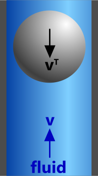
Fig 8. Falling Sphere
Vortex Calculator – Technical Help
Units
You may use any units you like, but you must be consistent.
Sub & super-scripts:
₁ = inlet
₂ = outlet
ƒ = friction
ₛ = sphere
ₐ = atmospheric
ₜ = tangential
ᴸ = loss
ᵀ = terminal
Bernoulli
This calculation option (Fig 9) calculates the expected flow characteristics of an incompressible fluid (i.e. a liquid) through a duct of constant section (e.g. a pipe or riser) according to Bernoulli.
Whilst this is a stand-alone calculation facility; and provides the fluid properties (ν, ρ and g) used in the other three calculation options, its primary function is to enable the user to calculate the feed rate of fluid (Q) through a pipe or riser for the forced vortex calculation option.
Length (L) and viscosity (ν) are used to define frictional losses in the pipe (hƒ and pᴸ).

Fig 9. Duct
Input Data:
'Duct' refers to a circular pipe or riser through which the fluid flows.
Ø = internal diameter of duct
L = duct length (L ≥ z₁ - z₂)
h₁ = inlet head; depth of fluid above duct inlet #
z₁ = inlet altitude of (upper) end of duct ##
z₂ = outlet altitude of (lower) end of duct ##
p₂ = outlet pressure; the ambient pressure preventing fluid outflow from the duct #
ν = fluid kinematic viscosity
ρ = fluid density
g = gravitational acceleration
pₐ = atmospheric pressure
# If you set the outlet pressure (p₂) at ambient (101325N/m², 14.7lb/in², etc.), you must add an equivalent head to the inlet (h₁): h = pₐ / ρ.g
e.g.
seawater; h₁ = +10.06903681 m (396.41877205 ins)
freshwater; h₁ = +10.32076273 m (406.32924134 ins)
## z₁ and z₂ may be relative to any common datum
Output Data:
A = duct internal area
Q = volumetric fluid flow rate (based upon v₂ ###)
p₁ = fluid pressure @ 'z₁'
v₁ = fluid velocity @ 'z₁'###
v₂ = fluid velocity @ 'z₂'
F = fluid outlet force
E = fluid outlet energy
P = fluid outlet power
Rᴺᵒ = Reynold's number
hƒ = head loss due to friction
Cƒ = friction coefficient
pᴸ = pressure loss
### velocities of an incompressible fluid at the inlet and outlet of any duct of constant cross-section will be identical. The difference identified here is theoretical, due to friction. The actual velocity is 'v₂'
Forced Vortex
The fluid flow calculated in the Bernoulli calculation option above may be used to define the dynamics of this vortex. You will have to copy and paste the data (Q) for input here (Q).
This calculation option has two functions; define the surface profile of the rotating fluid and identify the properties of the fluid at any point 'p' within it.
It is important to understand that whilst the maximum and minimum heights (h̆ and ĥ) of the fluid are accurately calculated, they only apply to a vortex in which the fluid volume remains constant, i.e. that there is no waste-flow, or that it is accurately controlled.
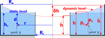
Fig 10. Forced Vortex
Input Data:
r = radius to point 'p' within the vortex
d = depth to point 'p' within the vortex
Rᵢ = inside radius (Rᵢ) of the fluid body
Rₒ = outside radius (Rₒ) of the fluid body
hₒ = static head of the fluid body
Q = fluid ingress flow rate
Output Data:
ω = angular velocity, which varies linearly with radius (r).
δh = maximum relative surface elevation
ĥ = [minimum] fluid depth @ 'Rᵢ'
h̆ = [maximum] fluid depth @ 'Rₒ'
h = fluid depth @ 'r'
vₜ = tangential velocity @ 'r' #
a = centrifugal acceleration of the fluid @ 'r' #
pc = centrifugal pressure of the fluid @ 'r' #
# applies throughout the fluid depth (@ 'r')
pd = gravitational pressure of the fluid @ 'd' ##
## applies throughout the fluid (@ 'd')
ζ = vorticity, which is constant throughout the fluid body, irrespective of radius or depth.
γ = hydrostatic condition; γ = -ρ.g (pressure per unit length).
In addition to the above calculation results, this option also provides the co-ordinates for the following plots;
radius vs tangential velocity and radius vs surface profile.
Free Vortex
The fluid properties used in this calculation are carried over from the Bernoulli calculation option (above).
An air-cone will be generated in a free vortex if the centrifugal pressure (pc) in the fluid is greater than the gravitational pressure (pg), which is why the air-cone profile-radius reduces with depth (d). Whilst tangential velocity (vₜ) is the same at any depth at a given radius (r), gravitational pressure (pg) increases with depth.
It is important to understand that whilst the air-cone described by this calculation is accurate and valid, it will close below a given depth (Fig 6; d) if the centrifugal pressure (pc) is insufficient to overcome surface tension within the peripheral fluid.
This calculation option has two functions; define the surface profile of the central air-cone and identify the properties of the fluid at any point 'p' within the fluid surrounding the vortex.
Vorticity in this calculation is always zero.
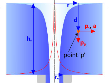
Fig 11. Free Vortex
Input Data:
r = radius to point 'p' within the vortex
d = depth to point 'p' within the vortex
rₒ = outlet radius
hₒ = head at 'rₒ'
Output Data:
vₜₒ = tangential velocity @ 'rₒ'
vₜ = tangential velocity @ 'r'
pc = centrifugal pressure @ 'r'
pg = gravitational pressure @ 'd'
δp = pressure differential @ 'r', 'd' (air-cone if negative)
K = constant of motion
ζ = vorticity {0}
In addition to the above calculation results, this option also provides the co-ordinates for the following plots;
radius vs tangential velocity and radius vs air-cone profile.
Falling Spheres
The fluid properties used in this calculation are carried over from the Bernoulli calculation option (above).
The purpose of this calculation option is to identify the upward (vertical) velocity of a fluid that will stop a sphere from falling through it; i.e. cause the sphere to sit suspended in the flowing fluid.
Input Data:
Ø = pipe [internal] diameter
Øₛ = sphere diameter
ρₛ = sphere density
Output Data:
Flow type: Stokes, Allen or Newtonian
mₛ = sphere mass
vᵀ = terminal velocity (of sphere)
Fᵀ = terminal force (on sphere)
Cd = drag coefficient (sphere)
β = Faxen-Oseen force factor
Rᴺᵒ = Reynolds number
Applicability
Vortices applies to all natural and unnatural vortices.
Accuracy
These calculationss are accurate - according to recognised theories - for all theoretical vortices. Their accuracy will, however, vary according to the level of disturbance present.
Further Reading
You will find further reading on this subject in reference publications(1 & 13)

