Weight Lifting Calculator
The simplest system that provides a mechanical advantage is the lever (Fig 1)
Give me a lever long enough, a fulcrum and a place to stand and I shall move the earth⁽¹⁾
but mechanical advantages may be achieved with other systems, such as ...
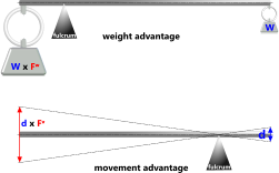
Fig 1. Simple Lever
Pulleys; of different numbers and diameters
Gears; of different diameter
Hydraulics; cylinders of different diameter
Screws; i.e. sliding a weight up a very shallow slope (thread helix angle)
... or any combination of the above.
The mechanical advantage for all of the above systems is defined by a factor (Fʷ)
i.e. W = F x Fʷ (Fig 1)
and (except the screw) movement (or velocity) advantage is its inverse (1/Fʷ)
Whilst the above systems are normally associated with lifting weights, they are much more useful than that. Their mechanisms can all be modified and/or combined to provide a mechanical operational advantage in complex machines.

Fig 2. Mechanical Advantage: Lever
For example:
A screw thread may be activated within a machine to apply a very strong lock on components that would otherwise move, or
An hydraulic cylinder may be activated to push a dowel into a slot or hole to prevent further movement, or
Pulleys and sheave-blocks may be used to tension chains and lifting equipment for trials and tests, or
Gears can be used in vehicles to increase or decrease rotary movement from an engine crankshaft
By reversing relative dimensions, you can change the advantage from weight (or force) to movement (Fig 1)
Mechanical Advantage Systems

Fig 3. Mechanical
Advantage: Pulleys
Lever
A bar supported at a fulcrum anywhere along its length about which it is permitted to swivel.
A weight (W) is hung at one end of the bar and a force (F) is applied to the other end. Movement at F will generate movement in W
The magnitude of the weight (W) and its movement relative to the applied force (F) are dependent upon relative lengths; ℓ:L (Fig 2)
Pulley
A grooved wheel (or roller; R) capable of containing a length of cord or belting that, when pulled, rotates the pulley (r). The two principle systems are the Torque pulley and Sheave Blocks.
The Torque Pulley is the simplest of the pulley systems that gains its mechanical advantage from the difference in radii between the input and output pulleys (R:r).
With a larger input pulley (or roller; R) the lift factor (Fʷ) will be greater than 1.0 which means that the weight lifted will be greater than the applied force.
With a smaller input pulley (or roller; R) the lift factor (Fʷ) will be less than 1.0 which means that the weight lifted will be lower than the applied force but movement will be greater.
There are number of variations to the pulley system, all of which increase the lifting capacity but reduce the weight’s relative movement. These include:
1) a detached (hanging) pulley that will double the lift factor (Fʷ)
2) two sheave blocks that contains multiple pulley wheels with which the lift factor (Fʷ) increases with the number of pulleys
3) the use of screws or multiple gears to rotate an input pulley, which significantly increase the mechanical advantage but at a significant cost in relative movement
Screw
The mechanical advantage of a screw is based upon the angle of the thread helix. Standard screw threads have a helix angle of between 2° and 4°, giving a mechanical advantage of ≈1/Tan(3°) {≈19}
The problem is of course that the input force at the end of the torsion bar must move a long way for any significant movement in the weight.
The most common use of this system is in screw jacks as they are required to lift exceptionally heavy weights and the finer the thread (pitch) the greater their mechanical advantage.
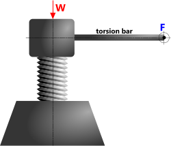
Fig 4. Mechanical Advantage: Screws
Gears
Gears and pinions provide the mechanical advantage as a result of their different diameters. String a number of gears together and significant additional gains can be made.
Whilst gears alone can offer a significant mechanical advantage, they may be combined with pulleys such that a force applied to an input pulley cord will rotate a small output pulley with a significantly improved advantage if used in conjunction with numerous intervening gear-sets.
The weight that can be lifted by the output pulley can be calculated thus: W = T ÷ r
and the torque can be calculated thus: T = F x R
Hydraulics
The most important advantage in using hydraulics to move a heavy weight or increase movement is that it can be done virtually remotely, i.e. the only thing connecting the input and output mechanisms is the fluid.
The mechanical advantage from a small input cylinder and a large output cylinder will be in the form of increased lift capacity.
The mechanical advantage from a large input cylinder and a small output cylinder will be in the form of increased movement.
Weight Lifting Calculator – Technical Help
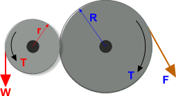
Fig 5. Mechanical Advantage: Gears
Units
You may use any units you like, but you must be consistent.
The output data is unit-free.
For example, whether or not you apply Imperial or metric units the output factors (Fʷ and Fᵛ) may be applied equally to metric and/or Imperial forces and movements (or velocities)
Output Data
Fʷ (weight factor) is a multiplier that you may apply to any input force (irrespective of units) in order to determine the weight lifting capacity of the system: W = F x Fʷ (Fig 2)
Fᵛ (velocity factor) is a multiplier that you may apply to any input movement (irrespective of units) in order to determine the movement (or velocity) of the weight at the output end of the system: D = d x Fᵛ (Fig 1)
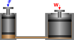
Fig 6. Mechanical Advantage: Hydraulics
Calculation Options
Torque PulleyThe simplest mechanical advantage system that involves pulleys; a large pulley that is attached to, and rotates together with, a small pulley.
A large input pulley (R > r) will provide a lift weight mechanical advantage
A small input pulley (R < r) will provide a movement mechanical advantage
A sheave block is a series of pulley wheels that are free to rotate independently on the same shaft. This lift configuration uses two sheave blocks, one above the other.
The mechanical advantage for the weight lifted is twice the number of pulleys per sheave block, where n = the number of pulleys per sheave block.
This calculation assumes that there is 1 full cord return (180°) for each pulley in both sheave blocks
i.e. offset angles; 'α' & 'β' are both zero (Fig 7)
If the offset angles; 'α' & 'β' are not zero, they are expected to be between 0° and 90°
A configuration with only one pulley (n = 1) does not need an upper sheave block unless an offset angle (α or β) is less than 0°
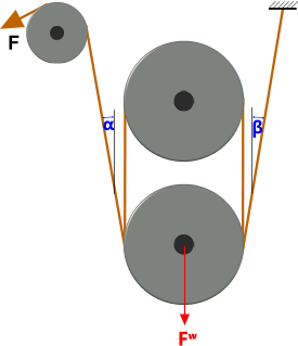
Fig 7. Sheaves Blocks
Whilst calculations for angles less than -180° are theoretically correct, such a configuration would need more pulley-wrap capacity than is available according to 'n'
Whilst calculations for angles greater than 90° are theoretically correct, such a configuration would result in a negative lift factor (Fʷ) if; n = 1
Differential PulleyThe same as a Pulley Block system but uses a cord in the form of a continuous loop.
A large input pulley (R > r) will provide a lift weight mechanical advantage
A small input pulley (R < r) will provide a movement mechanical advantage
A Pulley Block system that is driven by a worm & wheel. The worm & wheel provides a much greater weight lifting mechanical advantage than the Pulley Blocks, but at the cost of a much slower movement.
A large input pulley (R > r) will provide a lift weight mechanical advantage that will be significantly increased due to the additional mechanical advantage from the worm & wheel
A small input pulley (R < r) will provide a movement mechanical advantage that will be significantly reduced due to the additional mechanical disadvantage from the worm & wheel
An input pulley and an output pulley connected via a train of up to 5 gear sets. A gear set is a pair of gears that turn together on the same shaft.
A large input pulley attached to a small gear, then a train of large to small gears gives a mechanical advantage for lift weight
A small input pulley attached to a large gear, then a train of small to large gears gives a mechanical advantage for movement
The translation of rotary movement into linear movement along the axis of the screw.
The mechanical advantage is derived from the tangent of the screw thread helix
The simplest of all mechanical advantage systems.
If you enter a negative value for ℓ the weight will be hung between the applied force and the fulcrum, reducing the mechanical advantage
The difference between the diameter of the input cylinder and that of the output cylinder determines the mechanical advantage.
A larger output cylinder provides a mechanical advantage for lift weight
A larger input cylinder provides a mechanical advantage for movement
Applicability
The weight lifting calculator applies to any mechanism that requires a force or movement enhancement whether it is a stand-alone system or incorporated in a larger, more complex machine.
Accuracy
Weight Lifting is as accurate as the input data used, i.e. there is no margin of error.
Notes
- Archimedes (225 BC) actually said something closer to: "give me a fulcrum and place to stand and I shall move the earth", but it amounts to the same thing
Further Reading
You will find further reading on this subject in reference publications(?)

