Spur Gear Calculator
(tooth profile design and strength)
The gear calculator has been designed to help you optimise standard and non-standard spur gear configurations.
Pinion
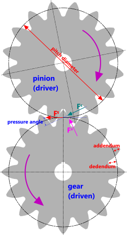
Fig 1. Pinion and Gear
The pinion is the driver (or input) gear wheel fitted to the electric or diesel motor output shaft and provides the rotary movement that will be transferred to the driven gear (wheel).
The pinion is usually (but not necessarily) the basis for sizing the driven gear. Its specification generally requires the following minimum information (Fig 1):
a) pitch diameter (Pᵈ), and...
b) total number of teeth (n), and...
c) pressure angle (θ), and...
d) wheel thickness (t)
the following additional information is normally also required
e) material strength
f) shaft diameter (including key dimensions)
If your pinion has non-standard tooth heights, you will also need to state the factor(s) to be applied to the addendum and/or dedendum. Standard Factors are as follows:
Addendum; Fᴬ = 1.0
Dedendum; Fᴰ = 1.25
See Hobbed Teeth vs Shaved or Ground Teeth below
Gear
The gear is the driven (output) wheel and has the same tooth height and pitch as the pinion.
If you state the properties of the pinion and the rotational ratio, your gear wheel may be designed fully with no further information, assuming it has the same thickness as the pinion.
Diametric Pitch (Pᵈ)
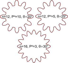
Fig 2. Tooth Profiles
All pinions and gear wheels are specified by defining the total number of teeth relative to the pitch diameter of the pinion or gear; the larger the number, the smaller the relative tooth height or the finer the pitch specification. Some typical configurations are shown in Fig 2.
The design standard ‘ANSI B6.1’ provides a list of recognised diametric pitches, the coarsest being ‘π÷10’ and the least coarse being 20. The standard's coarsest recognised fine pitch is 24 and their finest is 120. However, according to the standard a diametric pitch of 20 may treated as both coarse and fine.
Whilst you’re not limited to the ANSI standard’s recognised values, as intermediate pitches are perfectly acceptable from an operational and performance perspective, you may encounter problems with general interchangeability.
Pressure Angle
Preferred pressure angles (according to ANSI B6.1) are 20° and 25°, although they do recognise other angles for specialist applications. 14½° has been used in the past but is no longer recommended by the standard.
The principal problems associated with modifying the pressure angles outside the above recommended range of values (20° to 25°) are that:
a) reducing the angle will weaken the tooth due to reduced width at the root
b) increasing the angle will result in increased separation forces and reduced torque transfer
As such, CalQlata recommends that you try to stick to the recommended range of angles.
Forces
The force on the mating teeth (gear and pinion) is as a result of the torque applied by the pinion (Fᵗ, Fig 1). The two important components of this force are the contact or bearing force (Fᶜ), which will define the surface hardness of the material you require and the separation force (Fˢ) that will define the strength of your shafts.
Tooth Profile
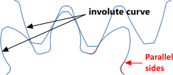
Fig 3. Mating Pinion & Gear Profiles
As pinion and gear rotate, their teeth should ‘roll over’ each other. There should be no relative sliding (abrasion) as this will cause excessive wear. This is managed by machining the contact surfaces (sides of the teeth) in the form of an involute curve. The involute curve is based upon the pinion and gear ‘base diameters’ (Øᵣᴾ and Øᵣᴳ).
As can be seen in Fig 3, mating gears of different diameters should have different profiles according to the appropriate involute curve for the diameter of the gear wheel concerned.
If your pinion or gear has a small diametric pitch (e.g. <6) and a small pressure angle (e.g. ≤20°) its teeth may be wasted at the root making them weak. Whilst a solution to this problem could be to machine the sides of the lower portion of the teeth with parallel sides (Fig 3), care should be taken when employing this modification to the tooth profile as it may result in excessive tip wear of the mating teeth if the rolling action is compromised.
Hobbed Teeth vs Shaved or Ground Teeth
If the teeth are hobbed or shaped using an accurate cutter the standard dedendum factor (‘Fᴰ’) of 1.25 is preferred as it keeps tooth depth to a minimum thereby minimising bending stresses.
If the teeth are pre-shaved, ground or cut with square tipped cutters, the dedendum factor (‘Fᴰ’) should be increased to 1.35 or even 1.4
Geared Rack
A rack is a gear-wheel of infinite radius, in other words; straight.
As such, its involute curve is also infinite (straight). Therefore, the contact surfaces of the teeth on a rack should be straight (flat) irrespective of the tooth profile of the mating gear.
Gear Wheel Material
Whilst you are free to use any material you like for a gear or pinion, even today, the best material for these applications remains carbon steel and alloys thereof.
Carbon Steels
Free cutting carbon steel (see Special Carbon Steels > Free Cutting) is preferred for gear wheel manufacture because of its good machining properties as a result of its sulphur content. Free cutting carbon steel also has the added advantage of increased strength due to its phosphorus content.
Case (or surface) Hardened: Together with the recommended carbon (C) content of 0.15% to 0.25% and the preferred manganese (Mn) content of between 0.4% & 0.7% the only currently available SAE carbon steel grade is 1120
Untreated: Together with the recommended carbon (C) content of 0.25% to 0.5% and the preferred manganese (Mn) content of between 0.5% & 0.8%, currently available SAE carbon steel grades are 1126, 1138, 1140, 1145 and 1151. The higher the grade, the harder the steel will be.
Through Hardened: Together with the recommended carbon (C) content of 0.4% to 0.5% and the preferred manganese (Mn) content of between 0.4% & 0.7% the only currently available SAE carbon steel grades are 1140 and 1145
Alloy Steels
Recommended alloy steel grades:
SAE 4130, 4140: Chromium based, medium carbon steel alloy (very high strength)
SAE 4360: Nickel based, medium carbon steel alloy (high strength)
SAE 4615, 4620: Nickel based, low carbon steel alloys (high ductility)
SAE 8615, 8620: Nickel & chromium based, low carbon steel alloys (high hardness low ductility)
SAE 9310: High nickel & high chromium based, very low carbon steel alloy (high strength high ductility)
Cast Gears
The preferred carbon steels for cast gears are SAE 0022 and SAE 0055 both of which can be hardened by carburising
Gear Wheel Manufacture
There are a number of manufacturing methods for gear and pinion wheels, e.g. milling, hobbing, shaving, grinding, casting, etc., however, it is always better to forge gear teeth and finish machine the surface profile after heat treatment, as this procedure significantly increases strength and reliability (design life) over fully machined or cast gear teeth.
Given that milling and hobbing requires the use of preformed tools and that these are expensive and that it is unlikely you will not have a tool for exactly the correct profile for pinion and gear, it is acceptable (for one-off assemblies) to use close approximations. Whilst the pitch and tooth depth must be exact, the profile radius may be within 90% of the theoretically correct dimension and the pressure angle should be within 2° in order to minimise operational wear.
Gear Calculator – Technical Help
This calculator is designed to follow the recommendations of the ANSI standard B6.1-1968, R-1974. Therefore all input dimensions must be in imperial units (lbf, ins and hp) as requested in the calculator.
There is only one calculation option in this calculator and all variations for straight-cut or spur gear wheels are possible within it.
Units
You may use any units you like, but you must be consistent.
Gear Design
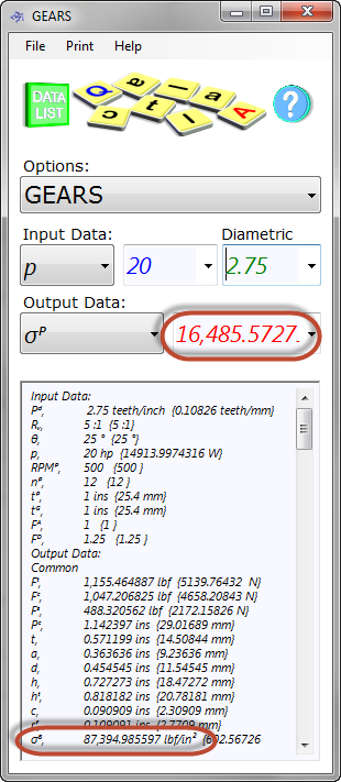
Fig 4. Typical Design Calculation
Sizing
You should size your pinion and its teeth to suit the recommended materials for gear wheel manufacture, e.g. carbon steel (see 'Material Selection' below).
Given that you have decided on using a free-cutting carbon steel (see SAE Special Carbon Steels, 11XX) for the pinion, the maximum permissible bending stress (σᴾ) must be less than or equal to the minimum specified yield stress for the material modified by a suitable utilisation factor.
Assuming the power input and rotational speed are pre-determined, you simply alter your diametric pitch (Pᵈ) and number of teeth (nᴾ), along with pinion thickness (tᴾ), until you achieve an acceptable bending stress (Fig 4)
Material Selection
As the strength of the recommended gear-material is between 33<65 ksi⁽¹⁾ for case hardened steels (Special Carbon Steels; 1120 & Plain Carbon Steels; 1020) and it is normal to impose a material utilisation factor of 0.5 to accommodate impact loads, when sizing your gear; you should alter your diametric pitch (Pᵈ) and number of teeth (nᴾ), along with pinion thickness (tᴾ), until you achieve a bending stress (σᴾ) somewhere between 16.5 and 32.5 ksi⁽¹⁾
Bearing stress (σᴮ) only applies to the surface of the material. If the bearing stress in your gear teeth exceeds the minimum yield strength of the surface material ‘flats’ will appear at the contact surface, the width of which will increase with the intensity of the over-stress. The following is a reasonable ‘rule-of-thumb’ material/treatment selection procedure:
1) If bearing stress is considerably higher than bending stress (σᴮ > 2xσᴾ), you should use case hardenable steel
2) If bearing stress is higher than bending stress (1.2xσᴾ < σᴮ ≤ 2xσᴾ), you should use through hardenable steel
3) If bearing stress is similar to bending stress (σᴮ < 1.2xσᴾ), you should use untreated steel
It is never a good idea to over-design gears for the following reasons:
1) Large gears consume more power and are less responsive to speed variations than small gears
2) The lower the minimum specified yield stress for your body material, the greater its toughness making it more tolerant to abuse⁽²⁾
3) The lower the surface hardness of the gear-teeth, the less likelihood they will crack and/or chip due to brittle fracture
It is normal to apply a utilisation of 0.8 to the surface hardness requirement
As hardness of carbon steels is directly related to strength and carbon content), once you know the bearing stress, you can predict with reasonable accuracy the associated hardness and therefore the amount of carbon you need in the surface of your material. For example;
If your bending stress is 16.5ksi and your bearing stress is 87.4ksi (Fig 4), as the bearing stress is considerably more than twice the bending stress you should use a case hardenable carbon steel. After applying the utilisation factor (0.8) to the bearing stress, the minimum yield strength of the surface material should be about 110ksi. From the SAE Plain Carbon Steels table it can be seen that the hardness associated with this yield stress is between BHN 229 (SAE 1066) and BHN 224 (SAE 1095) along with the associated carbon content between 0.7% and 0.9%. CalQlata would recommend selecting a conditional grade somewhere in the middle of the two, e.g. SAE 1075, which has the correct Mn range, ensuring a surface infusion of 0.85% carbon (BHN 231).
The ideal material for this application is therefore SAE 1120 with a carburised case of C: 0.85%, the depth of which is normally about:
0.01ins for a gear under low loading conditions
0.02ins for a gear under normal loading conditions and used occasionally
0.04ins for a highly loaded gear used frequently
A reasonable rule of thumb is; 0.01 + (1.0E-10 x number of revolutions during its design life) inches of hardness depth
CalQlata's Hardness Conversion calculator may be used to convert between various hardness scales.
Standard Calculation (according to the ANSI design standard )
Select one of the values provided in the ‘Diametric Pitch’ drop-box.
Set the pressure angle (θ) to 20° or 25° ⁽³⁾
Set the addendum factor (Fᴬ) to 1.0
Set the dedendum factor (Fᴰ) to 1.25
All other input data should be completed according to your requirements
Non-Standard Calculations
Whilst it is normally wise to select a value somewhere between the minimum and maximum limits recommended in the ANSI standard (π÷10 ≤ Pᵈ ≤ 120) you can of course enter any value you like in the ‘Diametric Pitch’ text-box taking care to ensure that the value entered does not result in badly wasted teeth (see Drawing Your Gear Teeth below).
Should you genuinely need to adopt a non-standard diametric pitch for your pinion-gear assembly that results in an unacceptable tooth profile, it may be possible to correct any shape peculiarities by altering the addendum and/or dedendum factors (Fᴬ and Fᴰ respectively).
In such a case, you should first attempt to achieve the desired result by modifying the two factors equally (normally reducing them by the same amount). If not, it may be possible to correct anomalies by reducing the addendum factor or the dedendum factor only.
Helical Gears
Helical gears are used to facilitate gear engagement and disengagement with minimal baulking, noise and or damage. The profile of helical gears are exactly the same as straight-cut gears but rotated through the helical angle.
The difference between helical gears and straight-cut gears is largely the fact that torque transfer is less efficient in that there is a third force-component trying to separate the gears laterally as well as radially. However, helical gears with little or no backlash will lose much less of the torque transfer than an assembly that allows for relative deflection through backlash.
Drawing Your Gear Teeth
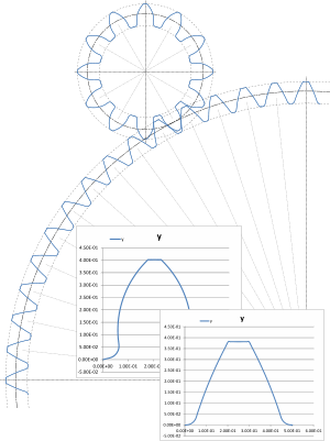
Fig 5. Drawing Your Pinions & Gears
The gear calculator provides ‘x,y’ drawing co-ordinates for both the pinion and the gear teeth. These are listed below the output data in the ‘Data Listing’ window. You simply copy and paste the lists into your preferred spreadsheet and use its chart generation procedure to draw them.
Refer to the Catenary technical help page for a plotting procedure using Microsoft’s Excel spreadsheet.
After producing this chart, you can save the chart to disk as an ‘emf’ file (enhanced metafile), reload it into your preferred graphics package, ‘ungroup’ or ‘open’ the metafile and delete all but the tooth profile lines.
You can then copy, paste and orientate each tooth according to its angular pitch, join them together and produce a complete or part gear⁽⁴⁾. We have generated the assembly shown in Fig 5 using ‘Excel’ and ‘Xara’ computer programs.
Input Data
p: power applied to pinion
Rᵥ: ratio of curvilinear velocity of pinion to gear at their pitch diameters (Øᴾ:Øᴳ)
RPMᴾ: rotational velocity applied to pinion
Fᴬ: factor applied to tooth addendum ('a'), which should be 1 for a standard (full-height tooth)
Fᴰ: factor applied to tooth dedendum ('d'), which should be 1 for a standard (full-height tooth)
Output Data
Common to Pinion and Gear:
θ: angle between the tangent at pitch diameter and the line of pressure on the tooth contact surface
Pᵈ: number of teeth per unit length at pitch diameter
Fᵗ: tangential force generated from applied torque
Fᶜ: contact force between mating teeth
Fˢ: radial force separating pinion and gear (pushing their shafts apart)
Pᶜ: curvilinear (circumferential) pitch-distance between adjacent teeth at pitch diameter
t: maximum circumferential tooth thickness (immediately above root radius)
a: addendum {top half of tooth - outside pitch diameter}
d: dedendum {bottom half of tooth - inside pitch diameter}
h: radial depth of tooth contact surface (working depth)
hᵗ: radial depth of tooth from inside diameter (Øᵢ) to outside diameter (Øₒ)
c: clearance between inside diameter (Øᵢ) of gear or pinion and outside diameter (Øₒ) of mating pinion or gear
rᶠ: fillet radius at root of tooth
σᴮ: maximum bearing (or contact) stress on tooth surface
Pinion Data:
tᶜᴾ: circumferential thickness of tooth at pitch diameter
rᴾ: profile radius of tooth (involute curve)
wᴾ: circumferential width of land on top of tooth
xᴾ: horizontal distance from centreline of tooth to centre of 'rᴾ'
yᴾ: vertical distance from centreline of tooth to centre of 'rᴾ'
Rᴾ: radial distance from centre of pinion to centre of 'rᴾ'
αᴾ: angular rotation of 'Rᴾ' from centreline of tooth to centre of 'rᴾ'
Øᵣᴾ: diameteral basis of involute curve
Øᵢᴾ: diameter at bottom of root radius of tooth
Øᴾ: pitch diameter of tooth
Øₒᴾ: outside diameter of tooth
Tᴾ: torque applied at pitch diameter
σᴾ: maximum bending stress in tooth
nᴾ: number of teeth
tᴾ: pinion [plate] thickness (tooth width)
Gear Data:
tᴳ: circumferential thickness of tooth at pitch diameter
rᴳ: profile radius of tooth (involute curve)
wᴳ: circumferential width of land on top of tooth
xᴳ: horizontal distance from centreline of tooth to centre of 'rᴳ'
yᴳ: vertical distance from centreline of tooth to centre of 'rᴳ'
Rᴳ: radial distance from centre of pinion to centre of 'rᴳ'
αᴳ: angular rotation of 'Rᴳ' from centreline of tooth to centre of 'rᴳ'
Øᵣᴳ: diameteral basis of involute curve
Øᵢᴳ: diameter at bottom of root radius of tooth
Øᴳ: pitch diameter of tooth
Øₒᴳ: outside diameter of tooth
Tᴳ: torque applied at pitch diameter
σᴳ: maximum bending stress in tooth
nᴳ: number of teeth
tᴳ: gear [plate] thickness (tooth width)
RPMᴳ: angular velocity
Accuracy
Whilst the output data in this calculator is completely accurate, i.e. no expected error, the ‘x,y’ co-ordinates for the pinion and gear may result errors of zero to around 0.001" and are therefore provided for drawing purposes only.
Whilst the calculated bending stress (σ₁ᴾ) in the tooth is as accurate as possible, bearing stress (σ₂ᴾ) is not so accurate. This is due to the fact that surfaces under high compressive load always deform significantly altering the contact area and therefore the resultant stress. Furthermore, bearing stresses are only valid for the surface of the materials in contact. They dissipate rapidly with depth (through the material). It is expected that the bearing stress calculated in GEARS, which is based upon ‘cam’ and ‘follower’ principle, should be accurate within ±10%
Bearing stress will always look high in theoretical calculations, but if it appears to exceed minimum yield strength for the material, this will not mean component failure, simply that the material will flatten locally until the contact area is sufficiently increased to bring the bearing stress down to yield.
Notes
- The maximum additional phosphorus of 0.04% in SAE grade 1120 (SAE Special Carbon Steels) will add 2.4ksi (0.04% x 6ksi) giving a minimum specified yield for the core material of 35.4 < 67.4 ksi
- This is only true if material quality is maintained
- For smaller diametric pitch values (<6) it is normally preferable to use 25°, otherwise either 20° or 25° is acceptable
- Remember to equalise the relative axis dimensions of your spreadsheet chart (measure them with a ruler) before saving the chart to disk
Further Reading
You will find further reading on this subject in reference publications(2 & 3)

