Structural Floor Calculator
(joist sizing)
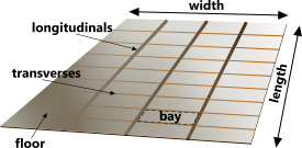
Fig 1. Typical Floor Construction
This calculator has been designed for the sizing of structural floor joists;
A floor is deemed to be an elevated rectangular plate or sheet (or floor boards) supported by equally-spaced longitudinal and transverse beams all of which are simply supported at both ends (see Figs 1 & 2)
The surface floor decking (plate, sheet or floor boards) is referred to as the 'floor'
The 'longitudinals' are the major support beams or joists running parallel to the length of the floor⁽¹⁾.
The 'transverses' are the minor support beams or joists running parallel to the width of the floor⁽¹⁾.
The area of floor enclosed by any two adjacent longitudinals and any two adjacent transverses is referred as a 'bay'
Permissible Deflection
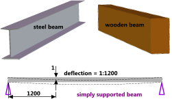
Fig 2. Typical Floor Beams
Floors are universally designed to deflect a specified amount with a maximum static design load per unit area (pressure) applied all over its surface.
This deflection is usually defined thus:
'deflection shall not exceed one in [length]'
For example: if a floor is designed to deflect; 1 in 1200 (Fig 2), this means that over a measured length of e.g. 6000mm in any direction the floor shall deflect no more than 5mm
This relationship applies to any units in which the floor is measured, inches, feet, mm, etc.
Materials
Whilst the most common floor construction materials are wood, steel and reinforced concrete, you can build your floor from any material(s) you wish provided it obeys Hooke's law.
Beam Supports
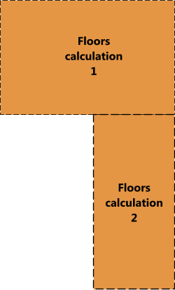
Fig 3. Irregular Floor Shape
Whilst the floor can be welded, screwed, nailed or otherwise fixed to its support beams, you should not assume that the beam ends are fixed or even guided, as apart from welding, these fixings tend to be unreliable. Therefore, whilst it is a conservative approach, Floors assumes that both ends of each beam are simply supported (see Fig 2)
Material Stresses
The floor calculator determines the stress in the floor material as a result of the design load per unit area and the maximum expected point load applied to the centre of a bay, but not for the support beams because their depths are unknown.
Floors manufactured from appropriate materials and designed to deflect within specified deflection limits are highly unlikely to achieve stresses anywhere near the yield stress for the material.
However, should you wish to identify the beam stresses, based upon the calculated minimum area moment, you can use the information generated by Floors to select an appropriate steel section from CalQlata's Steel Sections database or calculate the size of beam required in CalQlata's Area Moments calculator and thereafter identify its maximum stress using calQlata's Beams calculator (see Example Calculation below).
The Floor Calculator – Technical Help
Irregular Shapes
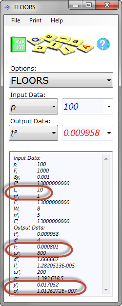
Fig 4. Floors Calculation
The floor calculator can also be used to calculate the material properties of a non-rectangular floor by breaking the overall shape up into regular rectangles and calculating each rectangle individually (Fig 3).
Longitudinals and Transverses
In Floors, you may, of course, run the longitudinals across the shortest dimension and the transverses across the longest dimension of your floor simply by entering a shorter length than width.
Units
You may use any units you like (p, F, E, etc.), but you must be consistent.
Input Data
Loads:
p is the design or specified maximum pressure that the floor can support over its entire surface without exceeding the deflection criteria; δy
F is the largest expected point load that will be applied to the floor, which Floors assumes will be applied in the weakest position, i.e. in the centre of a bay (Fig 1)
Dimensions:
L, W, nᴸ, nᵀ are the length and width of the floor and the number of longitudinals & transverses (respectively) that make up its dimensional matrix
Material Properties:
Tensile moduli; Eᴾ, Eᴸ, Eᵀ define the resistance to bending for the floor, longitudinal and transverse materials respectively
Deflection:
δy specifies the rate of deflection permitted per unit length of floor; e.g. 0.001 means that the floor may deflect no more than 1 in 1000
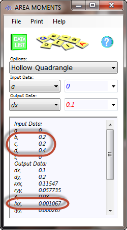
Fig 5. Area Moments Calculation
Output Data
tᴾ is the thickness of the unsupported section of floor material that will result in a deflection rate of no more than δy due to p
dᴸ & dᵀ are the spacings between the longitudinal and transverse beams respectively, which are defined by quantities; nᴸ, nᵀ
Iᴸ & Iᵀ are the second moments of area for the longitudinal and transverse beams respectively that will result in a deformation of no more than δy per unit length due to p
ωᴸ & ωᵀ are the loads per unit length supported by each longitudinal and transverse beam respectively as a result of p
yᶠ & σᵖ are the maximum deflection and maximum stress (respectively) that will be seen in the floor material due to F (Fig 4)
Example Calculation
A design pressure of 100N/m² and a point load of 1000N are to be applied to a 10m x 8m rectangular floor of 1 longitudinal beam and 5 transverse beams. All materials (beams and floor) will be manufactured from the same material, which has a tensile modulus of 1.3E+10N/m². The deflection for the entire floor shall not exceed 1:1000, i.e. δy = 0.001m (1 ÷ 1000)
Enter the above data as shown in Floors (Fig 4)
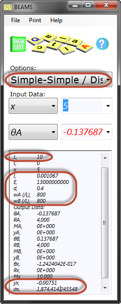
Fig 6. Beam Calculation
The minimum second moment of area for the longitudinal beam is 0.000801m⁴ (Fig 4).
Using CalQlata's Area Moments calculator, a beam of 0.2m x 0.4m has a second moment of area of 0.001067m⁴ (Fig 5) which is greater than 0.000801m⁴ and therefore will result in a smaller deflection than the design requirement.
If the appropriate information is entered into CalQlata's Beams calculator (Fig 6) the maximum bending stress will be 1.87E06N/m² (1.87MPa) and deflection will reduce to 1:1331 (L/yₓ: 10/0.00751), which is less than 1 in 1000.
The same calculation(s) can be performed for a transverse to find its maximum beam stresses.
Applicability
The floor calculator is applicable to all floors manufactured with any material assuming that the longitudinal and transverse beams are equally spaced and the flooring material is all-covering.
All calculations are applicable to floors comprising materials that obey Hooke's law.
The floor calculator assumes all loads are applied normal to the floor surface, all beams are simply supported and the flooring material is fixed (to the beams) at all edges.
Accuracy
All calculations are as accurate as can be expected using classical (Castigliano) theory upon which they are based.
Calculations are accurate only for floors comprising materials all of which obey Hooke's law.
Notes
- see Longitudinals and Transverses above
Further Reading
You will find further reading on this subject in reference publications(2 & 3)

