Upheaval Buckling Calculator
(buried pipelines)

Fig 1. Pipeline Upheaval Buckling
A pipeline under internal pressure and increased temperature (with respect to installation) will try to grow longitudinally. If this growth is restrained, the resultant axial compression will generate a longitudinal force in the pipe wall, which is generally referred to as an 'end-cap' force. Upheaval buckling is the term used to describe the vertical-upwards lateral displacement of a pipeline due to the lateral release of this compression that may or may not be a problem dependent upon circumstances (Fig 1).
This compression is proportional to the pressure and temperature in the pipeline. The end-cap force is at a maximum when displacement is zero and diminishes as displacement increases. As axial force is far more difficult to define CalQlata has limited the controlling parameter (input variable) to ‘growth per unit length’.
Upheaval buckling is usually intensified in cases where most of the pipeline is prevented from lateral displacement but is permitted to grow longitudinally, whereas a small section of the pipeline is free to displace laterally. In such circumstances all the potential axial growth in the pipeline will be concentrated over this small section amplifying displacement and bending stresses.
A pipeline with very little internal pressure (e.g. flow only) and minimal or negative temperature variation will not result in upheaval buckling unless the pipeline is of extreme length. In such pipelines expansion loops are normally provided at regular intervals to accommodate and control any growth.
Problem and Solutions
The most common problems associated with upheaval buckling in pipelines are listed below:
Anchors and trawl-boards
Bending stress
Scouring and vortex shedding
And the most popular solutions are as follows:
Lay pipeline in an arc
Lay pipeline in an open trench
Lay pipeline in a closed trench
Cover pipeline with something heavy (continuous or irregular)
Solution selection for any of the above problems is simply down to experience. The upheaval buckling calculator simply performs the calculations to assist with the selection process.
Anchors and Trawl-Boards
ProblemWhilst snagging as a result of dragging anchors or trawl-boards is a problem for any unprotected pipeline lying on the seabed, if lateral displacement lifts the pipeline off the seabed this problem is intensified. An anchor or trawl-board travelling along the seabed will pass under a raised pipeline dragging it along with the vessel, resulting in pipeline relocation at best and rupture at worst.
SolutionIn areas where these problems are likely, e.g. fishing regions in relatively shallow water all pipelines are usually laid in a trench. Whether or not the trench is open or closed is usually subject to cost. An open trench is normally cheaper to produce than a closed trench.
If trenching is impractical or expensive, overburden material (soil, rocks, mats, etc.) may be deposited on a pipeline laying on the surface. The weight of the cover or overburden must be sufficient to eliminate the lateral force per unit length. I.e. the weight per unit length of the overburden ‘must be greater than the lateral force per unit length generated in the pipe under consideration otherwise partial movement may occur under the overburden resulting in a gradual lessening of cover depth at this(these) location(s). Repeated growth cycles will subsequently result in the pipe pushing through the overburden at these locations, concentrating all of the growth locally and intensifying bending stresses and lateral displacement.
A closed trench need only be slightly wider than the pipe but should be deep enough to contain the pipe and the depth of overburden required for burial (Øₒ + Dᵇ).
Bending Stress
ProblemIf a pipe is allowed to move without constraint or is completely and sufficiently buried to prevent any axial growth and/or displacement, there will be no significant bending stresses in the pipe wall material other than those already present at installation.
Partial displacement will be concentrated/localised. I.e. all the growth in a pipeline (δℓ) may well occur as displacement over a relatively short length and dependent upon the configuration of the buckled region, such displacement could cause significant bending stresses.
SolutionBending stresses can be minimised by allowing total freedom or total restriction of movement and total freedom can be accommodated by laying the pipeline in a series of arcs (curves) allowing each ‘wave’ to bend and unbend in a controlled manner. Total constraint is achieved by adequately covering the entire length of the pipeline.
Where concentrated lateral deformation is expected to occur, it is necessary to calculate the likelihood of such stresses remaining within allowable limits. See the Calculation Considerations below.
Scouring and Vortex Shedding
ProblemScouring occurs where loose surface seabed material moves due to significant tidal or current flow. This can cause a pipeline to sink into the seabed or relocate, which may be a problem but does not normally cause upheaval buckling unless such movement forces axial compression into the pipe. Burial in such conditions is unreliable and suitable anchoring of the pipeline to the solid strata of seabed material adjacent to or beneath the scoured region is usually advisable. Such anchors should always permit controlled axial movement in order to minimise upheaval buckling.
If a pipeline has been laterally displaced vertically (lifted) or is spanning a ditch or valley and sits in fast flowing wind or water, fatigue can set in from low-cycle, high-level bending stresses or high-cycle, low-level bending stresses due to vortex shedding. Strategic burial or anchoring of the exposed pipeline is advisable in such circumstances (see CalQlata’s Vortex Shedding calculator).
SolutionSimilar solutions as those for anchors and trawl boards normally apply to these problems.
Trenches
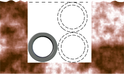
Fig 2. Open Trench
Trenches may be open or closed.
Open Trench
If a trench is open, it must be wide enough to allow the pipeline unrestricted movement over the trench floor, in which case it is essential to establish the behaviour of longitudinal growth in the trench (Fig. 2). As a general rule of thumb you should normally make an open trench at least twice as wide as the diameter of the pipe.
The minimum depth of an open trench need not be greater than the diameter of the pipeline if you are confident that the width of your trench is sufficiently wide to accommodate 100% axial growth. It is advisable, however, to allow for at least a full diameter of head-room above the pipe, increasing still further as trench quality reduces (Fig. 2).
If your open trench varies in altitude (i.e. the seabed surface undulates), your pipeline will almost certainly buckle vertically upwards at ‘hill crests’ and the length contributing to growth at these locations will be that between the basins of the two adjacent dips (or valleys) (Fig. 3). You should calculate the expected lateral displacement for this length of pipeline and bury it at the hilly crest which should cause lateral growth to push into the valley floor or displace laterally within the trench. See the Calculation Considerations below.
Closed Trench

Fig 3. Undulating Terrain
A closed trench has soil, rocks or mats covering the pipe. Whilst trench depth need not be greater or even equal to the minimum required burial depth plus pipe diameter, in areas where scouring and/or dragging objects may, over time, remove or settle the burial material reducing its effective depth, such regions may lead to localised lateral displacement.
This is generally regarded as the best method of pipeline protection.
Open Ground
When laid on a seabed or dry land a pipeline will normally follow the profile of the terrain and its growth will always follow the path of least resistance.
Exposed
A pipeline is normally left exposed (unburied) if external interference is extremely unlikely and/or if the terrain is relatively flat or level. Where this installation method is adopted, it is advisable to lay the pipeline in a large arc or arcs allowing growth and lateral displacement to occur equally over the entire length of the pipeline, thereby minimising bending stresses. Otherwise, the pipeline should be buried in part or in full.
This is the cheapest method of installation for any pipeline, and if laid on a flat or surface where external interference is unlikely it will also generate the lowest bending stresses.
Buried
Burial material alone is, in most circumstances, unable to prevent axial growth⁽²⁾
Where axial growth is fully or partially contained, lateral displacement will occur at the sites of least resistance. The weight of the burial material is used to prevent this lateral displacement.
Where the terrain supporting a pipeline is either undulating or otherwise does not accommodate large sweeping curves, suitably positioned burial mounds (berms) should be installed on the pipeline or it should be fully buried. The sizing and positioning of buried sections and/or berms should be such that growth is contained and/or directed to areas of safety. See Calculation Considerations below.
Inadequate cover (less than minimum required depth) will result in partial lateral displacement, which is a dangerous precedent as repeated partial displacement of a pipeline buried under rocks or soil will eventually push-through the cover material. It is always better to apply sufficient cover material to ensure all displacement is avoided.
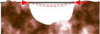
Fig 4. Freespanning Pipeline
When determining the quantity of burial material for ‘free-spans’ and/or elevated section (Fig. 4), you will need to consider loading from vortex shedding for the exposed lengths along with fluid forces due to seabed current or wind.
You should always bury pipelines much deeper at terrain peaks as these will be areas of concentrated growth.
Burial Material
The amount of material required to stabilise (prevent lift) a long pipeline is usually very small if it is all covered but if you leave any length of it inadequately buried, all the longitudinal growth will be concentrated in this unburied region which may result in significant lift and high bending stresses.
Burial material can be seabed silt, soil or rocks, or even manmade mats all of which will have different densities and shear angles (excluding the mats) and thermal insulation properties. Where vertical lift and lateral displacement are possible, the shear angle may be considered when determining overburden depth (see Shear Angle below).
Burying a pipeline will increase its thermal insulation raising its operational temperature. This increased temperature variation should be considered when calculating the expected growth in your pipe. A trench filled with soil in dense seabed material will have the greatest thermal insulating properties (see CalQlata’s Thermal Conductivity calculator).
In such circumstances you should ignore any cooling effect of the surrounding material. It is usually preferable to use rocks for burial, as opposed to soil, as at least some cooling is available from water permeating the aggregate and rock has a higher thermal conductivity than soil.The upheaval buckling calculator includes recommended (by CalQlata) densities and shear angles for some rocks and soils in various conditions.
Remember, if your calculations show that upheaval buckling in any of the above locations results in plastic strain, you cannot return the pipe to lay-flat conditions by removing the pressure and temperature that caused it, and subsequent cover will be proportionally deeper and proportionally more expensive. This is why it is always safer and cheaper to bury a pipe before start-up.
Rocks
Rock dumping is a term used to describe the placement of a specified overburden (cover depth) of small rocks sufficient in quantity to prevent lateral displacement of a pipeline under axial compression due to its weight.
Whilst there is no adhesion between rock particles, there is some interlocking capability, you may therefore apply a minimal shear angle when calculating the cross-sectional area for the overburden weight on the pipeline (see Shear Angle below).
The cooling effect of water and reduced thermal insulation properties, with respect to soils, may be taken into account when defining the long-term operational temperature of the pipeline buried under rock aggregate.
Soil
Soils vary in density and shear angle dependent upon consolidation and saturation. However, because soil quality varies considerably over a very short distance, unless available data dictates otherwise, it is always advisable to use small shear angles and a low densities in your calculations.
No cooling effect should be taken into account when defining the long-term operational temperature of a pipeline buried under soil.
Sand
Sand behaves like rocks, only slightly less dense but as saturated and dry sand grains have no adhesion and no interlocking capability you should use a shear angle of 0° for saturated or dry sand. If the sand grains are damp (not saturated) and on dry land, you may increase the shear angle to the minimum value recommended in the calculator.
It is unlikely that a pipeline will benefit from external cooling when buried under sand.
Calculation Considerations
The only variables in an upheaval buckling calculation are; the length of the pipline (L), how much of it will be subject to lateral displacement (ℓ) and the growth rate (δL/L) under operation, all other variables (Øᵢ, Øₒ, E, ν, μ, ρ, θ, etc.) will be constant for any given pipeline.
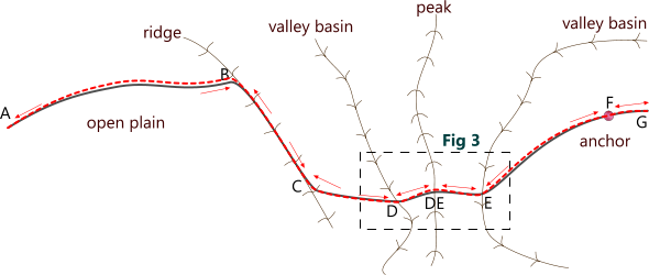
CalQlata recommends the following approach to length selection in your calculations associated with Fig. 5 as an example:
Total Length (ℓ = L)
You enter both lengths the same in the upheaval buckling calculator when your pipeline is ...
... buried from end to end
... shorter than 1000 diameters and laid in a straight line
... laid from end to end in the basin of a cleft or V-shaped valley that is otherwise flat (no undulations in the valley floor)
... laid in a trench less than 2 diameters wide
e.g. Fig. 5:
B-C this section is constrained by ridges meaning that lateral displacement may be vertically upwards. However, if this section is permitted growth past point B, it could be considered with the 'Zero Length' calculation option below
C-D the short straight length of this section means that either all or none of this section would be normally buried as it could otherwise buckle vertically upwards, one of its ends being up against a ridge and the other in a valley basin preventing axial displacement
F-G the short straight length of this section means that all of this section should be buried as it could otherwise buckle vertically upwards
Partial Length (ℓ < L)
When deciding on the section length (ℓ) for your calculation, you will need to identify points where growth/movement may be prevented and areas where free growth is allowed to occur. A typical pipeline with some common natural and unnatural anchors is shown in Fig. 5. See Example Calculation below.
Any part of a pipeline laid between natural and/or unnatural anchors on a flat open plain may be regarded as a Zero Length calculation (see below) unless it conforms to the parameters specified in 'Total Length' (above), in which case the length between anchors should be evaluated as a total pipeline length (L).
e.g. Fig. 5:
D-E both ends of this section dig into valley basins preventing axial movement so all axial growth would normally occur at the peak (DE) of the central ridge, which should be buried to prevent possible lift. The preferred length of the buried section should be entered into the upheval buckling calculator as 'ℓ' and the total length 'L' should be the length of the section between D and E
Zero Length
Open flat terrain where the pipeline is laid in one or more arcs. In such conditions, upheaval buckling may be ignored.
e.g. Fig. 5:
A-B the flat open plain and long arc configuation means that this section could be ignored as unconstrained growth will most likely occur evenly over the entire section length.
E-F the long arc configuation means that this section could also be ignored for the same reason as A-B
Upheaval Buckling Calculator – Technical Help
The Theory

Fig 6. Displacement Formula
Upheaval Buckling uses large deflection beam theory (Fig. 6) to calculate the expected lateral displacement (y) based upon all the axial growth in the pipeline (δL) being concentrated over the buckled section of pipeline (ℓ) along with the associated lateral force per unit length (ω) to achieve it.
If the calculated force creating the displacement (F̂) is greater than the force in the pipeline (F̌), Upheaval Buckling will recalculate the displacement based upon the force available from the axial growth (F̌).
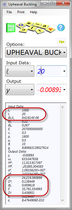
Fig 7. Example Calculation
Units
You may use any units you like, but you must be consistent.
Example Calculation (Fig. 7):
If you have a pipeline 1km long and you plan to bury all but 20m of this length, all of the 1km of growth will be concentrated in this 20m 'buckled' length. The calculation shows that the growth for the 10km pipe will be about 0.009618m over its entire length.
If all of this growth were to be released as displacement over 20m section the displacement would be 0.00893m and the resultant axial force in the pipeline would be 24,219.36N. The bending stresses (σᴬ & σᴮ) induced by the displacement are not significant (10.9MPa and 20.7MPa respectively) and the displacement of 9.6mm could also be regarded as inconsequential.
You will notice, however, when you reduce the buckled length (ℓ), displacement will also decrease but the stresses will rise. The opposite will occur as the buckled length increases.
You will also see that if you are able to bury the entire pipeline (set ℓ equal to L in Upheaval Buckling) that the depth of burial material required to stabilise your pipeline (Dᵇ) will usually be minimal but increases rapidly for the buckled length as it is shortened.
Input Data:
Pipeline Length (L): Length of pipeline between two anchors preventing longitudinal growth
Buckled Length (ℓ): Section of pipeline over which all the growth is concentrated
Axial Growth (δL/L): Axial growth (per unit length) generated by internal pressure and temperature increase (see CalQlata’s Pipe calculator)
Inside Diameter (Øₒ): Inside diameter of the pipe
Outside Diameter (Øₒ): Outside diameter of the pipe excluding insulation
Young’s Modulus (E): Elastic modulus of the pipe wall material
Poisson’s ratio (ν): Poisson’s ratio of the pipe wall material
Overburden Density (ρ): Density of the rocks, soil, sand, etc. used to cover the pipe. This figure should be reduced by 1000kg/m³ if installed on the seabed
Friction Coefficient (μ): Frictional resistance between the pipeline outer surface and the burial material (steel & rock ≈0.35; steel and clay ≈0.5; steel and sand ≈0.2; plastic and rock ≈0.25)
Shear Angle (θ): Internal friction in the burial material (see Shear Angle below)
Gravitational Acceleration (g): This value is used in the calculation to establish overburden material depth and should be set to '1' when using mass values in your calculations for force (e.g. lbf/in², kgf/m², etc.)
Output Data:
Deflection (y): Maximum potential lateral deflection in the buckled length at ℓ/2
Lateral Force (ω): Force per unit length in pipeline generating lateral displacement
Bending Moment (Mᴬ): maximum bending moment in the pipeline at ℓ/2
Bending Moment (Mᴮ): maximum bending moment in the pipeline at anchor or lift-off point
Bending Stress (σᴬ): Bending stress in the pipeline at 'Mᴬ'
Bending Stress (σᴮ): Bending stress in the pipeline at 'Mᴮ'
Axial Force (F̂): Axial compressive force generating lateral displacement (y)
Bending Depth (Dᵇ): Minimum depth of burial material above pipeline required to prevent lateral displacement (varies inversely with pipe length)
Axial Growth (δL): Total growth in the pipeline (δL/L x L)
Axial Force (F̌): Axial compressive force generated by Axial Growth (δL/L)
Cover Depth (Dᶜ): Minimum depth of burial material above pipeline required to prevent growth by frictional resistance between pipe and burial material (constant for any pipe length). This value will be unrealistically high for steel pipe as it is almost impossible for burial materials to prevent growth through frictional resistance
Elastic Function (k): √F/EI
Error Margin (ε): The calculation error achieved in the iteration of minimum force (F̂)
Shear Angle
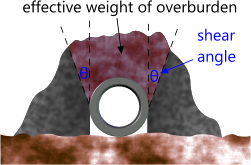
Fig 8. Shear Angle
All burial materials exhibit a shear angle (Fig. 8) dependent upon dampness, grain-size, etc. This angle will vary between 0° (saturated and loose seabed silt) and 45° (sand, rocks, etc.). However, the shear angle you may use to replicate the spread of material lifted with the pipeline must include the effects of adhesion/cohesion.
For example: When dry, sand will exhibit a shear angle of almost zero (0°) when pulling or pushing a pipeline through it, whereas hard, damp clay may exhibit a shear angle well over 45°
The menu item ‘Help>Technical’ page in the Upheaval Buckling calculator provides various recommended shear (internal friction) angles for expected materials and conditions.
Applicability
This program applies only to subsea and dry-land pipelines.
The formulas used to determine the lateral force and consequential deflection have been modified for large deflection (flexible) beam theory.
This calculator is limited to pipelines with a growth rate (δL/L) between 1E-10 and 0.7
Accuracy
The error margins in Upheaval Buckling are normally <±1E-10
However;
They only apply to pipelines whose stresses remain within the elastic region
If your calculation has reversed the polarity of either one or both of the bending moments (Mᴬ or Mᴮ) the calculation will have resulted in a reversed loop and the results, whilst accurate, will be unrealistic for a pipeline. CalQlata has not yet managed to generate this polarity flip despite many attempts to do so.
It is also important to ensure that you use the correct pipeline length (L) in your calculations as deflection is inversely proportional to length. I.e. expected lateral displacement increases with decreasing calculated length and vice-versa, and a pipeline laid on uneven ground may encounter physical anchors in the terrain reducing the effective length you should consider.
Notes
- Axial compression in a plain beam of constant cross-section is covered by CalQlata’s Column Buckling calculator.
- The axial force in a pipeline growing as a result of temperature and pressure increase is normally too high to be wrested by the frictional resistance between the pipe and the weight of burial material. Therefore, if a pipeline is allowed to expand longitudinally at one or both ends of a buried section, it will do so, and this growth will be almost total, irrespective of the buried length.
- 'Partial' cover refers to the length not depth. When burying a pipe you must always use the correct depth but you may select strategic section lengths to bury in order to encourage growth in areas that do not represent a problem.
Further Reading
You will find further reading on this subject in reference publications(4)

