Colebrook and Fanning Friction Factors
Colebrook Friction Factor

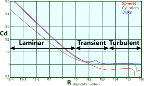
Fig 1. Reynold's Number vs Drag Coefficient
The Colebrook equation provides friction factors recommended for shape coefficients such as drag with particularly rough surfaces that are in contact with fast flowing (turbulent) fluids and generate Reynold’s numbers greater than 4000 (Fig 1).
However, this friction factor may equally be applied to transient and even laminar flow conditions if safety and/or senstivity are important.
(see Application Example below)
Whilst the Colebrook factor directly affects surface drag it also (indirectly) affects added mass and essentially to the same extent. As such, this factor should be applied to the added mass coefficient (Ca), but not to displaced mass (technical help page Fig 1), which will always remain 1.0.
Fanning Friction Factor
The Fanning friction factor is used in calculations for flow through a pipe.
Like the Colebrook friction factor, the Fanning friction factor should always be applied to rough surfaces and turbulent flow, but unlike the Colebrook factor, it is also normally applied to upper transient levels of fluid flow; i.e. for Reynold’s numbers greater than 2000 (Fig 1)

Fig 2. Colebrook & Fanning Friction Factors
The Fanning friction factor is related to the Colebrook as shown in Fig 2 and applied in the following formula:
F = (4.ƒᶠ.L.v²) / (2.Ø.g)
Where:
F = loss in head
L = length of pipe
Ø = diameter of pipe
v = velocity of fluid
g = gravitational acceleration
CalQlata's Pipe Flow calculator automatically generates the Fanning friction factor for each calculation, but it is not included in our Pipe Flow+ Calculator (API RP 14E). The change in head loss as a result of the Fanning friction factor can be applied retrospecively to the results from Pipe Flow+ as follows:
F' = F . (1-ƒᶠ)
Colebrook Calculator – Technical Help

Fig 3. Colebrook Calculation
Application Example
As described in our Added Drag technical help page, you can expect a drag coefficient (Cd) of between 0.5 and 0.7 for a circular pipe in slow to average flow conditions.
E.g. the Added Drag calculator predicts a drag coefficient of 0.674792 for a 0.5m diameter pipe with a perfectly smooth surface
(e.g. ϵ ≤ 0.0000004m)
If, however, the surface of this pipe deteriorates through corrosion and damage such that it comprises multiple roughened pits and crevices of up to 4mm (0.004m), and is immersed in a turbulent flowing fluid, e.g. seawater @ 2m/s, the drag coefficient for the above pipe in this condition (e.g. ϵ = 0.004m) becomes 0.861959, it is to this value that Colebrook’s friction factor should be applied, i.e.;
Cd' = Cd . (1 + ƒ)
The Colebrook friction factor (ƒᶜ) for the above pipe and flow conditions is 0.035198 and the flow is turbulent (Fig 3). The modified shape factor is calculated thus:
Cd' = 0.861959 x (1 + 0.035198) = 0.892298233
This same modification should also be applied to the added mass coefficient.
Under normal circumstances this additional factoring is considered unnecessary for laminar and transient conditions, which air flow of the same velocity over the above pipe would generate, but it would be inadvisable to disregard it for any less-than-smooth surfaces, irrespective of flow conditions.
Reynold’s Number
If you are only interested in calculating Reynold’s number, you can ignore the surface roughness value (ϵ) as it is not used in this calculation, however, you need all of the input data to determine either/both friction factor(s) (ƒᶜ &/or ƒᶠ)
Units
You may use any units you like, but you must be consistent.
Metric and Imperial units are provided {metric, Imperial} below for information only.
Input Data
Ø (diameter): The nominal diameter of the corroded pipe, external or internal dependent upon whether or not the fluid is flowing over the pipe of through it, or the width of a flat surface {m, ins}
μ (dynamic viscosity): This is the resistance of the immersed or entrained fluid to dynamic shear {N.s/m², lb.s/in²}
v (velocity): the velocity of the fluid relative to the rough surface {m/s, ins/s}
ρ (fluid density): The mass density of the flowing fluid {kg/m³, lb/in³}
ϵ (surface roughness): The maximum depth of the undulations in the surface over which the fluid is flowing {m, ins}
Output Data
ƒᶜ (Colebrook friction factor): The Colebrook friction factor {no units}
A value for all input data is required for this output
ƒᶠ (Fanning friction factor): The Fanning friction factor {no units}
A value for all input data is required for this output
Rₑ (Reynold's number): The Reynold's number for the conditions of the flowing fluid {no units}
A value for all input data except surface roughness (ϵ) is required for this output
Applicability
The Colebrook friction factor applies to the drag and added mass coefficients of any external surface when exposed to turbulent fluid (Rₑ>4000) and rough surfaces
The Fanning friction factor applies to the loss of head due to friction from turbulent or transient fluid flow (Rₑ>2000) through a circular pipe with a rough surface finish
Accuracy
Colebrook and Fanning friction factors are calculated using an iterative procedure and will be within ±1.0E-08 if the calculation is successful.
Unsuccessful results are possible if the input data is unreasonable, in which case an error message will appear
Reynold’s number is exact
Further Reading
You will find further reading on this subject in reference publications(3 & 12)

