Plain Bearings Calculator (Journals)
A plain bearing or Journal is a solid sleeve inside which a shaft is expected to rotate with acceptable precision (location and guidance) and no metallic contact. Plain bearings are also referred to as bushes, although bushes tend to be sleeves in which a central shaft slides or rotates at slow speed. They are normally used for location purposes only.
Plain bearings are usually manufactured from materials that will wear before the shaft for reasons of cost; i.e. a worn bearing is usually cheaper to replace than a worn shaft.
Whilst these bearings may be manufactured from any material, low friction materials such as copper alloys (see material uses) are usually considered most suitable due to the inevitable fact that some metallic contact will occur during their design life. Sintered bearings are frequently used as the material is porous; i.e. they can hold oil and/or graphite nodules both of which are excellent lubricants.
Plain bearings are used where the available thickness precludes the use of low-friction bearings such as roller and ball type or where low temperatures must be maintained, very high loads are possible or for reasons of cost.
Low-Friction Bearings vs Plain Bearings
Both bearing types have their place in the world. The benefits and issues with each are outlined below.
Low-Friction Bearings
Low-friction bearings (roller or ball type) offer minimal power loss and excellent response. They work better with grease lubrication than with oil and are usually sealed, i.e. there is no lubricant flow. The reason for sealing low-friction bearings is that their open structure would otherwise admit loose particles thereby accelerating wear and ultimate failure. They also work with almost no clearance, i.e. they offer much greater positioning accuracy than plain bearings.
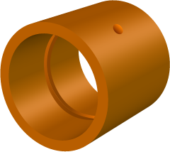
Fig 1. Typical Plain Bearing
The problems with low-friction bearings are that they will fail without notice and such failures can be catastrophic. Bearing cages will most likely collapse quite quickly after the first signs of excessive wear removing all support from the shaft.
The lack of flow means that heat cannot be easily removed from the bearing during operation causing the lubricant to lose much of its viscosity, and therefore its ability to protect the bearing from wear. Heavy loads are avoided with this kind of bearing because of the nature of the contact when loading balls and rollers.
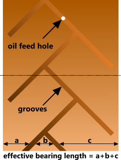
Fig 2. Complex Groove Pattern
Plain Bearings (Journals)
Due to the much greater contact area with plain bearings, they can support much higher loads than low-friction types. Plain bearings are, however, much more susceptible to dimensional changes as a result of temperature variations, which can result in locking up or unacceptable levels of play. It is therefore essential that temperatures are controlled at a level where lubricant viscosity can be assured and dimensional changes are minimised. This is usually achieved by pumping oil into the centre of the bearing through one or more feed holes under sufficient pressure to maintain a minimum film thickness and sufficient flow rate to accommodate loss through the ends of the bearing. This flow will help to reduce the temperature of the oil and maintain its viscosity. Intricate groove patterns will ensure that oil is distributed to all parts of the bearing in adequate measure.
Plain bearings normally require a lubrication supply and collection system that includes pump(s), distribution piping, collection trays(s), filters, cooling facilities, etc.
Correctly designed and maintained plain bearings will usually show signs of wear long before catastrophic collapse.
Lubrication
Oil is best suited to plain bearings for the reasons described in Plain Bearings (Journals) above.
Unlike low-friction bearings, Journals could theoretically last indefinitely if all the dimensional and running characteristics are correct and exact, which would be possible if there is always a minimum oil film thickness between the bearing and the shaft, in other words, no metallic contact between the two during their design life.
Oil is normally fed into a Journal by way of one or more small feed hole(s) and distributed around the shaft via a central groove (Fig 1). More complex groove patterns are sometimes used where running clearances are tight, the lubricating oil is very viscous and/or very high speeds are required (Fig 2). Such groove patterns ensure much freer oil flow than a single groove and are normally unidirectional.
The grooves in a Journal reduce its effective length as shown in Fig 2. Where such complex groove patterns are used it is advisable to try and keep the effective length similar all around the Journal, otherwise you will create areas of dissimilar oil pressure.
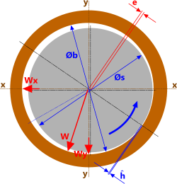
Fig 3. Minimum Film Thickness
Minimum Film Thickness
The minimum acceptable thickness for the film of oil between the shaft and the bearing must be less than or equal to the radial clearance with the shaft in the centre of the bearing and greater than their combined surface roughness. If you wish to reduce the film thickness still further you will need to improve the machining quality on the shaft and/or the bearing.
Unless machined to perfection, all shafts exhibit an element of imbalance that will manifest itself as a radial force (see CalQlata's Shafts program) and which needs to be supported by the pressure of the oil in the bearing. This support will innevitably result in a reduced film thickness (Fig 3), the minimum of which (ĥ) defines the performance characteristics of the Journal.
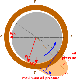
Fig 4. Maximum Oil Pressure
If the minimum oil thickness is too great, it would be difficult to maintain the flow required to provide the necessary oil pressure. Too small and the oil temperature would rise reducing its viscosity and therefore its lubricating effectiveness. Moreover, the smaller the minimum oil film thickness the greater the drag on the shaft and the greater the resultant power drain.
The maximum oil pressure in the Journal occurs between the radial load (W) and the minimum film thickness (ĥ). The pressure in the oil around the rest of the bearing annulus will be close to ambient, dependent upon viscosity and radial clearances (Fig 4).
The calculated oil flow rate only applies to the minimum film thickness area. The actual flow rate will be higher and will need to be corrected in practice.
Calculation Method

Fig 5. Bearing Loads
There are a number of calculation techniques for plain bearings, all of which demonstrate varying levels of accuracy and/or applicability. The calculation method selected by CalQlata is based upon that proposed by Michell and Cardullo because it has been verified by NACA (report 1157) but which applies only to Journals with an effective length up to twice the internal diameter.
A typical calculation procedure is as follows:
1) Calculate the Radial Force (F) due to the eccentric imbalance of your shaft (Fig 5) at design speed (CalQlata's Shafts program)
2) Identify F₁ and F₂ (Fig 5) as they may each require different bearing dimensions (CalQlata's Beams program)
3) Select suitable machining tolerances for your shaft and bearing (CalQlata's Limits and Fits program)
4) Identify the maximum surface roughness for both shaft and bearing either from your preferred machining methods or direct measurement and then perform the following calculation sequence for both minimum and maximum metal conditions
5) Determine the minimum acceptable film thickness (ĥ), which must be greater than the combined surface roughness of the of the shaft and bearing, and the maximum film thickness, which must be less than or equal to the radial clearance ( [Øb-Øs]÷2 ). If you cannot find an acceptable match for either your minimum or maximum metal conditions, you should reduce the surface roughness of the shaft and/or the bearing by improving machining quality
6) Calculate the characteristics for your bearing-shaft assembly using Journals with an estimated dynamic viscosity for your lubricating oil at the anticipated operating temperature
7) Compare the force (W) from calculation 6) above with force (F₁ or F₂) from 2) above. If they are not the same, you can alter the bearing length and/or oil viscosity until they match. If you cannot match the radial forces, you will need to modify your shaft design to reduce its dynamic amplitude (i.e. improve its balance).
Temperature Rise
There are many methods for predicting temperature increase in the lubricant as a result of internal shear, but as oil pressure will vary (largely unpredictably) around the circumference of the bearing and along its length, and having studied many of the calculation methods (formulas), CalQlata has insufficient confidence in any of them to be included in the Journals calculator.
However, as a rule-of-thumb; assuming all your design, installation and operating conditions are correct, and you are using an oil-flow lubrication system, your oil should not exceed 20°C (≈70°F) above ambient.
Journals Calculator – Technical Help
The design of plain bearings (Journals) is an iterative process. You calculate the amplitude and radial force of your shaft and compare the results with those calculated in Journals. If they don’t match, the design won’t work so you will need to modify the dimensions and/or properties of the system until it does work (see Example Calculation below).
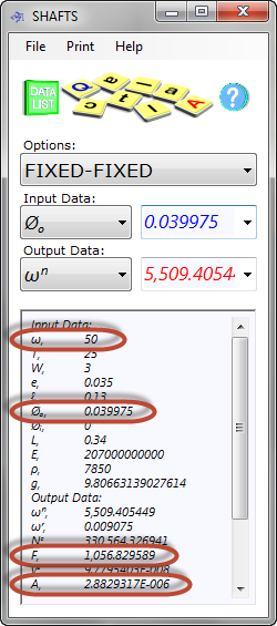
Fig 6. Shaft Calculation
Units
You may use any units you like, but you must be consistent.
Input & Output Data
Whilst the Journals calculator provides a great deal of output data (all of which are described in the calculator), much of it is for information only. The most important output data for the design of your Journal is listed below:
P: Power drain due to shear in the lubricating oil in the region of minimum oil thickness
W: Applied load in the Journal should match that from your shaft
Qᵣ: Minimum volume flow rate is that required to maintain maximum pressure
p̌: Maximum pressure is that required to resist the load applied by the shaft
If you can’t get the loads to match for your required bearing length, machining tolerances (MMC) and oil viscosity, you will need to modify your shaft design.
Example Calculation
A shaft of 40mm x 340mm long requires a close running fit, and the associated machining tolerances (CalQlata's Limits and Fits program) are as follows:
Class: H8/f7
Diameter: 40mm (1.5748ins)
Hole max, 40.039mm (1.5763ins)
Hole min, 40mm (1.5748ins)
Shaft max, 39.975mm (1.5738ins)
Shaft min, 39.95mm (1.5728ins)
The maximum metal condition of the assembly give a shaft OD of 39.975mm and a bearing ID of 40mm
The preferred machining method for the shaft is cylindrical grinding, which gives a maximum surface roughness of 0.0016mm (1.6μm)
The preferred machining method for the bearing is boring, which gives a maximum surface roughness of 0.0063mm (6.3μm)
Together, these show a combined surface roughness of 0.0079mm
The radial clearance in the bearing is (40-39.975)/2 = 0.0125mm
Therefore, the minimum film thickness must be: 0.0079mm < ĥ ≤ 0.0125mm
Assuming a minimum acceptable safety margin for surface roughness of 1.2; the calculation iteration will start with a minimum film thickness of 0.0095mm
CalQlata's Shafts calculator (Fig 6: metric units of Newtons and metres) shows that at 50 RPS with a 3N load, 35mm from its centreline and 130mm from one end, a radial force of 1056.83N (107.77kgf) will be imposed on this shaft.
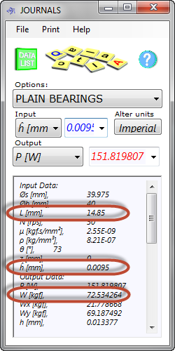
Fig 7. Plain Bearing Calculation
CalQlata's Beams calculator shows the reactions to this force at each end of the shaft will be:
F₁ = 711.47N (72.55kgf) and F₂ = 345.36N (35.22kgf)
Enter the correct dimensions and performance characteristics for the shaft and bearing into the Journals calculator (Fig 7) and alter the bearing length until you have the same load (W) as you have for amplitude in the Shafts calculator (note: dynamic viscosity is estimated as 2.55E-09kg.s/mm²).
For a bearing length of 14.85mm, the load (W) is 72.534kgf, which is sufficiently close to F₁ (72.55kgf). If you wish to provide oil-way grooves in this bearing totalling, say, 3mm width, your actual bearing will need to be 17.85mm wide. However, if this is considered to be too small to provide sufficient location/guidance for the shaft, you can either increase the minimum film thickness and/or reduce the dynamic viscosity of the lubricating oil until you achieve the desired results.
Your final results should of course provide you with an operating pressure and flow rate suitable for your supply system. Moreover, if, as with this calculation, the loads on both ends of the shaft are different, it may be that you will need to have different bearing lengths at each end in order to match the different end loads in the shaft.
Applicability
The calculations in Journals are applicable to plain bearings with or without grooves (as long as their widths are discounted in the bearing lengths) and the bearings are less than twice the diameter of the shaft. Accuracy will begin to fall off as the length of the bearing increases over and above this length. The Journals calculator does not apply to unusual plain bearing designs where 'through' longitudinal channels are machined into their bore.
Accuracy
Calculation results from Journals are not definitive. The theory is based upon a proposal by Michell and Cardullo, which according to NACA shows the best correlation with practical results and is frequently used in the aeronautical industry.
Whilst it is not possible to provide an exact or accurate margin of error for Journals, NACA’s experimentation appears to show a general correlation of well within ±5% for most applications.
Further Reading
You will find further reading on this subject in reference publications(1, 3, 4 & 12)

