Second Moment of Area Calculator
(complex shapes)
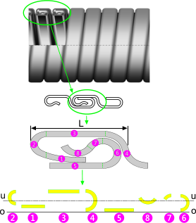
Fig 1. Complex Composite Cross-Section
A composite shape (or section) is a collection of individual sub-sections that together, when specifically positioned and rotated, constitute a complex shape with very different structural properties to the sum of those for each individual sub-section. They must be combined using their moments about specified axes to find their composite structural properties, which is what this moment of inertia calculator does for you. All you have to do is position and rotate each sub-section with respect to one or two axes at right-angles to each other.
In order to calculate the structural properties of a composite shape, you need to break it down into calculable sub-sections, which you then position and rotate with respect to one or two designated axes ('o-o' & 'r-r' see Axis Convention below). Sub-sections can be approximated if individually they have little effect on your final result. For example, 'Interlocking tube' (Fig 1) is used for, amongst other things, flexible pipe compression resistance and has a very complex section. If, for example you want to know how much compression the tube will support you can equate the composite section to an equivalent solid pipe wall thickness and use conventional formulas (or CalQlata's HydroLapse calculator) to determine its limiting hydrostatic collapse strength.
The cross-sectional area of the above mentioned interlocking tube could be broken down into convenient shapes making it relatively easy to calculate. Approximations are shown for sub-sections ❶, ❷ and ❹, all of which would be acceptable for axis 'u-u' but the approximation for sub-section ❹ would not be acceptable for axis 'v-v' because its width will have a significant effect on the final result and this dimension has been significantly altered.
In the above example, the only structural properties we are interested in are those with respect to the horizontal axis ('u-u'), so you need only input rotations (i.e. 'α' Fig 2) and relative vertical positions (i.e. 'r' Fig 2) for each sub-section. All horizontal positioning (i.e. 'o' Fig 2) can be left blank or set to zero.
Axis Convention
CalQlata has adopted the following axis convention for Area Moments and this moment of inertia calculator (Fig 2):
Area Moments
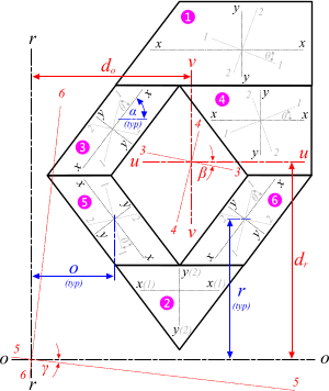
Fig 2. Multiple Axis Convention
1-1 is the principal horizontal axis for a sub-section (through its centre of area)
2-2 is the principal vertical axis for a sub-section (through its centre of area)
3-3 is the strong/weak axis for a sub-section (x-x axis rotated through θ)
4-4 is the weak/strong axis for a sub-section (y-y axis rotated through θ)
Area Moments+
u-u is the principal horizontal axis for the composite section (through its centre of area)
v-v is the principal vertical axis for the composite section (through its centre of area)
5-5 is the strong/weak axis for the composite section (u-u axis rotated through β)
6-6 is the weak/strong axis for the composite section (v-v axis rotated through β)
o-o is the offset horizontal axis for any composite or sub-section
r-r is the offset vertical axis for any composite or sub-section
7-7 is the strong/weak axis for o-o axis rotated through γ
8-8 is the weak/strong axis for r-r axis rotated through γ
When you have your result for Iᵤᵤ (second moment of area about the 'u-u' axis), you enter this value into formula: t = [12 x Iᵤᵤ / L]⅓ (where L is one pitch length of the composite section, see Fig 1), and you will have an equivalent standard pipe wall thickness that can be incorporated into your hydrostatic collapse strength calculations much more easily.
Polar Moment of Inertia
The polar moment of inertia of any shape (complex or otherwise) is the sum of any two complimentary second moments of area (at right-angles to each other)
i.e. Ixx+Iyy, I₁₁+I₂₂, Iᵤᵤ+Iᵥᵥ, I₅₅+I₆₆, etc.
Sum of Moments
The sum of any two complimentary second moments of area (at right-angles to each other) for any given shape about the same centre (where the two axes meet) will always be equal.
Second Moment of Area Calculator+ - Technical Help
Units
You may use any units you like, but you must be consistent.
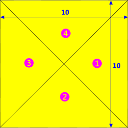
Fig 3. Complex Shape
It is easier to take you through a typical calculation than to try and explain the operation of this second moment of area calculator (Area Moments+) in abstract terms, so we have chosen an example that is simple to calculate (when compared to the interlocking tube shown in Fig 1) and easily verifiable.
In order to demonstrate positioning shapes in two directions and rotations in this second moment of area calculator (Area Moments+) we have chosen to construct a square from four right-angle triangles. The final product can be verified using the simple formulas: I = b.d³/3 (about axes 'o-o' and 'r-r') and I = b.d³/12 (about axes 'u-u' and 'v-v').
Moment of Inertia Calculation Example
Our example calculation will be to; calculate the structural properties a of a square of dimensions ‘10x10’ by combining four equilateral triangles.
Step 1: Create a sketch of your square (Fig 3)
Step 2: Divide the square into sub-shapes; in this case: a single triangle will be used four times to make up the complex shape (a square) (Fig 4)
Step 3: Calculate the structural properties of the triangle (Fig 4) using Area Moments+ e.g.:
α = 45
b = 10
h = 5
t = 0
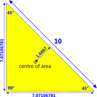
Fig 4. One Triangle
Step 4: Generate the positional dimensions for each sub-section manually or using a spreadsheet (Fig 5) e.g.:
❶ o = 8.33333; r = 5; ζ = 90°
❷ o = 5; r = 1.66667; ζ = 0°
❸ o = 1.66667; r = 5; ζ = 270°
❹ o = 5; r = 8.33333; ζ = 180°
(dimensions 'r' and 'o' running parallel to the axes concerned)
Step 5: Open Area Moments+ and clear all its data (menu item; 'File>Load Data>Clar all Data'). Open the data import facility by selecting menu item 'File>Load Data>Data-Import'.
Step 6a: If you used CalQlata’s area moments calculator to determine the structural properties for the triangle ...
You should see four icons with pale blue backgrounds; one for each of your area moments calculations (Step 3 above). Click your left-hand mouse button whilst your cursor is over each icon in turn and they will turn green (Fig 6), indicating that the relevant input data (A, Ixx, Iyy & Ixy) has been loaded into Area Moments+ for each of the four chosen sub-sections (01, 02, 03 & 04). In this example the relevant input data will be the same for all four sub-sections.
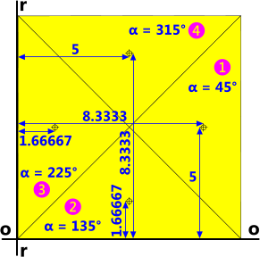
Fig 5. Construction Diagram
Step 6b: If you calculated the structural properties manually ...
You will need to enter the relevant dimensions for each of the four sub-sections {01, 02, 03 & 04} manually. In this case the relevant input data will be identical for each sub-section, i.e. you only need to calculate the structural properties for one triangle (see Step 3 above).
Step 7: Enter the positioning and orientation data (o, r & ζ) for each sub-section (see Step 4 above)
That's it….!
You will have created a '10 x 10' square (Fig 5) and calculated all of its structural properties about two sets of axis one set designated by you (the edges of the square in this example) and the other set passing through the centre of area of the square.
By way of verification:
Both second moments of area of this square about its centre of area are defined by the simple formula: b.d³/12 (10 x 10³ / 12) which equals 833.3333 (Fig 6)
Both second moments of area of this square about its edges are defined by the simple formula: b.d³/3 (10 x 10³ / 3) which equals 3,333.3333 (Fig 6)
Distances to the centre of area (dₒ and dᵣ) are both 5.0, the strong/weak axes (5-5 and 6-6) about its centre of area (u-u and v-v) should be rotated through 0° and the strong/weak axes (7-7 and 8-8) about its edge (o-o and r-r) should be rotated through 45°
All of which are easily verifiable.
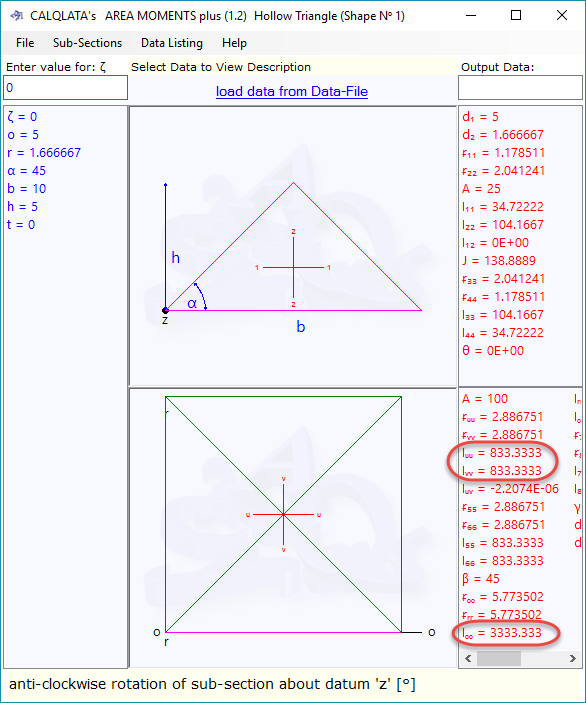
The above example is the default calculation in Area Moments+, which can be accessed via its internal menu item 'File>Reset Default'
Input Data
The input data for each sub-shape is the same as that for CalQlata's Area Moments calculator, apart from the first three entries for each shape which represent;
ζ: the shape's anti-clockwise rotation about its own centre of area
o: the horizontal distance from the vertical offset axis to the shape's own centre of area
r: the vertical distance from the horizontal offset axis to the shape's own centre of area
The axes 'u-u' and 'v-v' are the neutral axes through the complex shape's centre of area, and its strong-weak axes about the same point are; '3-3' and '4-4'
The axes 'o-o' and 'r-r' are your chosen neutral axes offset from the centre of area, and its strong-weak axes about the same point are; '5-5' and '6-6'
Data File: The Area Moments+ Data File contains all input and output data for all sub-sections. However, the composite results are listed only once at the end of the file. Use of this file is as described in How They Work but access to it in Area Moments+ is via menu item 'File>Load Data>Load' and 'File>Open Data File'.
If you load this data file (menu item 'File>Load Data>Load') it will overwrite all sub-section input data (Manual-Data and Imported-Data) with that stored in the Data File.
Should you wish to keep any particular Data File for future use, you should open folder 'Libraries\Documents\My Documents\calqlata' (or 'C:\Users\[your username]\Documents\My Documents\calqlata') and rename 'Area Moments plus.txt'. You can reset its name to 'Area Moments plus.txt' later when you want to use it again.
Applicability
This calculator applies to all sub-shapes as defined in Area Moments.
Accuracy
Accuracy of your results is directly related to the accuracy of the data entered. For example:
If the value 8.33333333333333…. is shortened to 8.333333 accuracy of the final calculation result will be similarly affected (Fig 6).
Further Reading
You will find further reading on this subject in reference publications(2 & 4)

