Velocity and Acceleration Calculator (trajectory)
Whilst velocity and acceleration formulas are numerically exact, their predictions are only as accurate as the information entered. In the real world, motion is virtually unpredictable in a mathematical sense due to the fact that almost nothing moves with constant acceleration. However, you can correct for this unpredictability with increasing levels of accuracy by making a few assumptions and approximations with the input data you use in the formulas.
For example:
If you want to know how long it will take a car to traverse a town, you simply need to assume that the car is travelling at an average speed of say 20mph.
If you want to know how fast a ball will roll down a hill, you simply assume that the vertical acceleration is a constant rate of 'g' (gravitational acceleration) multiplied by the 'Sine' of the slope (g.Sin[θ]) with a specified initial 'in-line' (see 'Note 1' at the bottom of this page) velocity.
See 'Notes' at the bottom of this page for the effects of rolling resistance on the above.
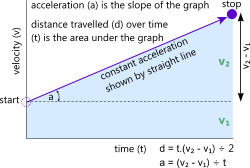
Fig 1. Linear Relationships
Whilst you can calculate the path of a projectile shot into the air, it will always be subject to the vagaries of the surrounding atmosphere, which is neither still nor predictable. However, you can make a few assumptions in order to average out these discrepancies and your results should be pretty accurate.
Travelacc works on the basis of such assumptions and averages.
Linear Motion
In the velocity and acceleration calculator, linear motion means movement in a straight line (from 'Start' to 'Stop': Fig 1). During this transit, the body will take a period of time ('t') to cover a specific distance ('d'). The difference between initial and final velocities (v₁ and v₂) either of which could be zero, negative or positive, is generated by a constant acceleration ('a').
The acceleration is simply the slope of the graph shown in Fig 1 and the distance covered by the body is the area under the same graph.
Rotary (or Angular) Motion
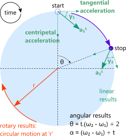
Fig 2. Rotary Relationships
Rotary motion means angular movement (imagine the speed with which the hands of a clock travel around its face, one complete turn is 360º or 2πᶜ) and it works in exactly the same way and with the same formulas as linear motion. All you have to do is replace:
linear distance ('d' see Fig 1) with angular distance ('θ' [degrees or radians] see Fig 2)
linear velocity ('v') with angular velocity ('ω' [degrees or radians per second])
linear acceleration ('a') with angular acceleration ('α' [degrees or radians per second²])
During its movement, a body will rotate a specific number ('θ') of degrees or radians, which is the 'angular distance'. The time ('t') it takes to rotate through this angle will define the angular velocity ('ω') of the body. The difference between initial and final velocities (ω₂ - ω₁) either of which could be zero, negative or positive, is generated by a constant acceleration ('α'), which can also be zero, negative or positive.
If you enter a value for radius ('r') in the velocity and acceleration calculator, it will also calculate the circular distance, velocity and acceleration at the specified radius between start and stop (see Fig 2).
Every rotating body is subject to tangential and centripetal accelerations (see Fig 2), the resolution of which is a linear acceleration (Start: 'a₁ᴸ', Stop: 'a₂ᴸ') on the body at an angle from the tangent; Start: 'γ₁', Stop: 'γ₂'.
Trajectory Path
Galileo declared that the trajectory of a projectile under the influence of gravity is parabolic, which is not strictly true. Not only is it incorrect mathematically (see Laws of Motion), the influence of atmospheric gases alters this trajectory from any mathematically predictable curve. The velocity and acceleration calculator determines the actual trajectory taking the effects of atmosphere into account.
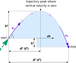
Fig 3. Trajectory Motion Path
A trajectory means a path a projectile will trace, initially rising at an angle and then falling back to earth under the influence of gravity (sometimes called ballistic path). See Fig 3
In a vacuum there would be no atmospheric drag on the projectile and the resultant distance travelled will be much further than on earth. Furthermore, without the influence of wind the aim would be straight and true.
However, in the real world, any projectile is subject to interference from the surrounding atmosphere. The velocity and acceleration calculator assumes that immediately after the initial force is applied to the projectile, there is a uniform vertical deceleration pulling it back to earth and a constant horizontal velocity towards the target. Along with the effect of the air and the wind (see Fig 5), it is the combination of these two properties that define the projectile's trajectory.
Where there is no wind, the velocity and acceleration calculator assumes the projectile will be slowed down as a result of drag in both horizontal vertical directions, ultimately reaching terminal velocity in the vertical downward direction. As there is no facility for altering medium density with altitude, any projectile calculated as having exceeded an altitude of ≈5km (≈3m), where the atmosphere is thinner, will predict shorter distances than expected.
The path of a projectile will be deflected if it is exposed to wind dependent upon its direction, which is specified in degrees of rotation about the aim-path of the projectile. A wind direction of 0° means that the wind is travelling from the lift-off location (Figs 3 and 4 'Start') towards the target (Figs 3 and 4 'Stop') along the aim-path (tail-wind). A wind direction of 180° means that the wind is travelling from the target towards the lift-off location against the aim-path (head-wind). A tail wind will push the projectile further along the aim-path and a head-wind will force the projectile to fall short of the target along the aim-path. All angles between 0° and 180° mean there will be an aim-path foreshortening or lengthening component and also a lateral drift component. The drift component will push the projectile to one side of the target. The distance travelled by the projectile will be similar along the aim path but 'offset' by the energy imput by the wind resulting in a slightly increased distance travelled at angle θ↔ (see Figs 4 & 5)
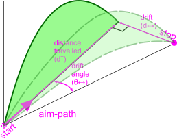
Fig 4. Wind Effects on Trajectory
Velocity and Acceleration Calculator - Technical Help
Units
You may use any units you like, but you must be consistent.
As with all CalQlata programs, you can put anything you like into the program and it will have a go. It will also warn you if your input data is 'unconventional'. However, especially with the Trajectory calculation option, you should be careful when entering:
1) negative values which could result in errors if not correctly matched with associated input values and the velocity and acceleration calculator would have no way of knowing
and
2) whilst it will give you a result that is theoretically correct if you enter a greater target height (hᵀ) than the trajectory peak height (hᴾ), Travelacc will also warn you. The resultant 'time' and 'distance' to the target will both be negative.
Linear
You need to enter three (not two or four) input data values (even if one of them is zero) to calculate.
Entering minus values in this calculation option will generate correct results, but be careful, the results may be meaningless if you haven't correctly matched them with your other inputs.
Rotary
This calculation option works in exactly the same way as the 'Linear' option (see Linear above). You enter what you know and the velocity and acceleration calculator will fill in the unknowns but for angles as opposed to distances. However, if you also enter a value for the radius ('r'), Travelacc will calculate the rotary (or circumferential) velocities (v₁ᴿ and v₂ᴿ), acceleration (aᴿ) and distance (dᴿ) at that radius. In addition to this, Travelacc will also calculate the linear accelerations (a₁ᴸ and a₂ᴸ) on the body at the Start and Stop velocities along with the angles (γ₁ and γ₂) these accelerations make with the tangent of the path (see Fig 2). If the angular acceleration is zero (i.e. ω₁ = ω₂), γ₁ will be the same as γ₂ and they will both be equal to 90º.
Trajectory
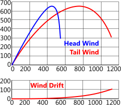
Fig 5. Wind Drift Effects
This calculation option is relatively straightforward. You simply apply an initiation energy ('E') to a specified object ('m' and 'A') and Travelacc will trace its path to a target point (Stop) at your specified elevation (hᵀ) where it will impact with energy 'Eᵢ'
Always check that your target height (hᵀ) is lower than the trajectory peak height (hᴾ) otherwise your answer will be incorrect.
The effects of drag and inertia from the surrounding atmosphere included in this calculation are directly dependent upon the density (ρ) you enter. For your assistance, the density of air is approximately 1.293kg/m³ (or 0.0000467lb/in³) and seawater is 1025kg/m³ (or 0.037lb/in³).
The wind velocity (vᵂ) and direction (θᵂ) should be applied according to the description in Trajectory Path above and the resultant drift particulars are as shown in Figs 4 & 5.
Fig 5 show the difference between a head and tail wind on a typical trajectory path
(drift plot shown for tail wind only).
Plotting Your Results
This calculation option includes a co-ordinate plot facility (Fig 7), in that if selected, the co-ordinates for: time (t) and 'x,y,z' and arc (s) distances from initiation to target will be listed below the output data.
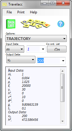
Fig 6. Trajectory Calculation
Note: The last co-ordinate plotted will always be below the entered relative target height (hᵀ)
You may copy these co-ordinates into your preferred spreadsheet in order to generate plots of the trajectory. The technical help page for our catenary calculator describes the procedure to follow for Microsoft’s Excel spreadsheet.
Dependent upon your spreadsheet capability, it may be necessary to switch the co-ordinate listing from Columns to Rows in your spreadsheet in order to generate the appropriate plot configuration. Fig 7 shows the trajectory plot for the calculation in Fig 6
A projectile travelling very fast may cover a significant drop in elevation during the entered time-step (tᵢ) on impact and no matter how much you alter the relative height of the target (hᵀ) within this altitude variation you will find that the calculation procedure and the co-ordinates remain unchanged. I.e. you will need to reduce the calculation time-step and/or interpolate between the last two co-ordinates should you require more accurate information.
You may set any time-step (tᵢ) you wish as long as the total number of calculations does not exceed 10,000. The smaller this time-step the more co-ordinates will be generated and the more accurate will be your final impact details. An error message ('tᵢ > {entered value}') will appear if this maximum value is exceeded, in which case you must increase the entered time-step (tᵢ) until the error disappears.
For example the calculation and plot pictured in Fig 6 & 7 gives 'z' values for the last two co-ordinates of 10.94235m and -1.566874m (0.1 second time steps)
Whereas if you reduce the time-steps for the same calculation to 0.01 seconds, 'z' values for the last two co-ordinates are 0.2982769m and -0.9684377m
And reducing the time-steps for the same calculation still further to 0.002 seconds (anything smaller and the maximum number of co-ordinates would be exceeded) and the 'z' values of the last two co-ordinates are 0.1487568m and -0.1046078m, which is about as accurate as can be expected for a trajectory of almost 1.5km
It is therefore quite possible that the number of co-ordinates generated may take some time to list in the data window, which can be frustrating given the automatic calculation facility of our programs. Therefore, each time the Trajectory option is selected or the calculator is loaded, the option to list co-ordinates is automatically deselected. It is always better to make your changes without generating this list until you have achieved your desired results (output data) then click the 'List Co-ords' button to generate the co-ordinates. Click it again to deselect this option.
Applicability
Linear and Rotary calculations have no applicability limitations.
Travelacc makes the following assumptions for the 'Trajectory' calculation option, which commensurate with a roughly spherical or cylindrical projectile.
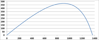
Fig 7. Trajectory Plot
Coefficient of drag (Cd) = 0.7 and coefficient of added mass = 1.0 (see Added Drag)
These calculations are valid for steady-state wind velocity. If you expect gusts, you should estimate an equivalent steady-state velocity for the period the projectile is airborne.
Notes
- 'in-line' means parallel with the slope (e.g. of the hill)
- Rolling resistance is usually given as a force and can be applied to a theoretical 'in-line' acceleration by the formula: a = g.Sin[θ] - F/m (where a = 'in-line' acceleration, g = acceleration due to gravity, θ = slope (of the hill), F = rolling resistance & m = mass of the ball) (see Note 3).
- If rolling resistance is specified as a horizontal resistance the formula in Note 2 above should be modified as follows: a = g.Sin[θ] - F/m.Cos[θ]
- In the above formulas, θ is positive for down-hill and negative for up-hill.
- If your results from the above formula(s) are negative, this means the ball will slow down immediately after initial velocity. If the initial velocity is zero and the resultant acceleration is negative it means the ball will roll backwards. If the initial velocity is zero and the acceleration is zero, the ball will not move.
- This subject is planned for an as yet unnamed future program, along with frictional resistance.
Further Reading
You will find further reading on this subject in reference publications(2)

